V&V Article 5: Modeling Dispersive Materials Using EM.Tempo
Contents
Introduction
In this verification & validation (V&V) article, we will demonstrate EM.Tempo’s ability to simulate models and structures containing dispersive materials. In a dispersive material, the constitutive parameters εr and μr of a material vary with frequency. The parameters' frequency dependency can be due to the natural properties of the material, or dispersion can be used as a type of macromodeling to abstract the behavior of a certain structure. The latter is often the case in metamaterials, where a structured array of periodic unit elements made of well-behaved material collectively appear to exhibit dispersive properties.
The dispersive properties of a dispersive material are often discussed in terms of its poles. In EM.Tempo, materials can be modeled using a set of Debye, Drude or Lorentz poles. EM.Tempo can also model uniaxial materials with both electric and magnetic dispersions based on any of the pole types mentioned earlier. A complete dispersive model of this type is required for representing metamaterials with doubly negative refractive indices (DNGs).
Reflection from an Infinite Slab of Dispersive Water
Perhaps the most familiar dispersive material is water, whose relative permittivity varies as a function of frequency. Water can be modeled by a Debye material. The complex permittivity of a Debye material with N poles is given by:
- [math] \varepsilon (\omega) = \varepsilon_\infty + \sum_{p=1}^N \dfrac{\Delta \varepsilon_p}{1 + j\omega \tau_p}, \quad \Delta \varepsilon_p = \varepsilon_{sp} - \varepsilon_\infty [/math]
where [math]\varepsilon_{\infty}[/math] is the value of the permittivity at infinite frequency, [math]\tau_p[/math] is the relaxation time corresponding to the pth pole having the unit of seconds, and [math]\varepsilon_{sp}[/math] is the value of the static permittivity (at DC) corresponding to the pth pole. [math]\Delta \varepsilon_p = \varepsilon_{sp} - \varepsilon_{\infty}[/math] represents the change in permittivity due to the pth pole. Water has a Debye pole with parameters τ = 9.4×10⁻¹² s, εs = 81 and ε∞ = 1.8. In this example, we consider a laterally infinite slab of water with a finite thickness of 6mm. A periodic unit cell with lateral periods of 3mm along both X and Y directions are assumed.
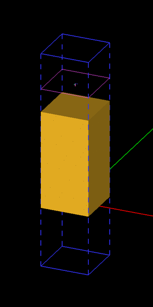
Figure 1 shows the geometry setup for the periodic unit cell of the water slab in EM.Tempo. The top and bottom domain walls are assumed to be convolutional perfectly matched layers (PML). The periodic structure is excited using a normally incident plane wave source.
The table below summarizes the simulation parameters:
| Center Frequency | Bandwidth | Grid Spacing | Termination Criterion |
|---|---|---|---|
| 20GHz | 40GHz | 0.1 mm | -100dB |
Figure 2 shows the results for the reflection coefficient of the water slab as computed by EM.Tempo and compares them to the analytical data given by Ref. [2]. A very good agreement between the two data sets is observed.
 Figure 2: Reflection coefficient of the water slab. Solid line: results computed by EM.Tempo, symbols: analytical data presented by Ref. [2]. |
Drude Plasma Slab
Next, EM.Tempo's periodic boundary condition will be used to simulate a plasma slab with infinite extents in the X and Y directions, but a finite Z-thickness of 1.5 cm. The Drude model often provides a good abstraction for an isotorpic non-magnetized plasma. The complex permittivity of a Drude material with N poles is given by:
- [math] \varepsilon(\omega) = \varepsilon_{\infty} - \sum_{p=1}^N \dfrac{{\omega_p}^2}{\omega^2 - j\omega \nu_p} [/math]
where [math]\omega_p[/math] and [math]\nu_p[/math] are the angular plasma frequency and angular collision frequency corresponding to the pth pole, respectively, and both are expressed in rad/s. For an isotropic non-magnetized plasma, [math]\varepsilon_{\infty} =[/math] 1. A Drude pole with ωp = 1.803×10¹¹ rad/s, and νp = 2×10¹⁰ collisions/s is used as the dispersive model for this project.
Figure 3 shows the geometry setup for the periodic unit cell of the Drude plasma slab in EM.Tempo. A box of dimensions 10mm × 10mm × 15mm is considered, with lateral periods of 10mm along both X and Y directions. The top and bottom domain walls are assumed to be convolutional perfectly matched layers (PML). The periodic structure is excited using a normally incident plane wave source.
The table below summarizes the simulation parameters:
| Center Frequency | Bandwidth | Grid Spacing | Termination Criterion |
|---|---|---|---|
| 40GHz | 60GHz | 0.1 mm | -100dB |
Note that, due to the infinite nature of ε as frequency approaches zero in the Drude model, the excitation bandwidth is set up to avoid the very bottom of the band. Also, since energy in the low end of the band may take a very long time to dissipate (the magnitude of the conductivity is very high here), we set a relatively stringent termination criteria. Figures 4 and 5 show the results for the magnitude and phase of the reflection coefficient of the plasma slab as computed by EM.Tempo and compare them to the exact data given by Ref. [1]. Figures 6 and 7 show the results for the magnitude and phase of the transmission coefficient of the plasma slab as computed by EM.Tempo and compare them to the exact data given by Ref. [1]. A very good agreement between the two data sets is observed in all the figures.
 Figure 4: Magnitude of the reflection coefficient of a plasma slab (as modeled with a Drude pole). Solid line: results computed by EM.Tempo, symbols: data presented by Ref. [1]. |
 Figure 5: Phase of the reflection coefficient of a plasma slab (as modeled with a Drude pole). Solid line: results computed by EM.Tempo, symbols: data presented by Ref. [1]. |
 Figure 6: Magnitude of the transmission coefficient of a plasma slab (as modeled with a Drude pole). Solid line: results computed by EM.Tempo, symbols: data presented by Ref. [1]. |
 Figure 7: Phase of the transmission coefficient of a plasma slab (as modeled with a Drude pole). Solid line: results computed by EM.Tempo, symbols: data presented by Ref. [1]. |
Sandwiched Cross-Dipole Slot Frequency Selective Surface (FSS)
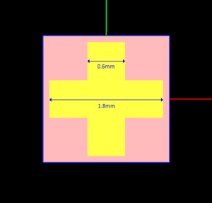
In the third example, we will model a sandwiched frequency selective surface (FSS) structure described in Ref. [2]. This periodic structure consists of a cross-dipole patterned metallic layer sandwiched between two Debye material layers. The Debye layers have an equal thickness of 2.5mm. The periodic unit cell has equal periods of 2mm along both X and Y directions as shown in Figure 8. The cross-dipole slot consists of two orthogonal rectangles with a length of 1.8mm and a width of 0.6mm as shown in Figure 9. The total thickness of the FSS structure is 5mm.
In this project, the Debye pole has parameters τ = 5.27×10⁻¹⁰ s, εs = 5.2 and ε∞ = 3.7. The table below summarizes the simulation parameters:
| Center Frequency | Bandwidth | Grid Spacing | Termination Criterion |
|---|---|---|---|
| 5GHz | 10GHz | 0.1 mm | -100dB |
The transmission coefficient of the dispersive FSS computed by EM.Tempo is shown in Figure 10. The computed data matches the HFSS results presented by Ref. [2].
 Figure 10: Transmission coefficient of the sandwiched cross-dipole slot FSS. Solid line: results computed by EM.Tempo, symbols: HFSS data presented by Ref. [2]. |
In order to better understand the effect of the metal-slot FSS, it was removed from the structure of Figure 5 and the remaining thick Debye layer (h = 5mm) was simulated using EM.Tempo. The computed results for the reflection coefficient of the combined Debye layers without the metal-slot FSS are shown in Figure 11, where the EM.Tempo data are compared again to the HFSS results presented by Ref. [2].
 Figure 11: Transmission coefficient of the combined Debye layers without the metal-slot FSS. Solid line: results computed by EM.Tempo, symbols: HFSS data presented by Ref. [2]. |
Nano-Plasmonic Solar Cell
The fourth structure to be considered in this article is a periodic nanoparticle-coated solar cell structure. A silicon-dioxide substrate is coated with an array of patterned silver-particle cuboids, which can be modeled with two distinct Debye poles. The nanoparticles are used to increase the optical absorption within semiconductor solar cells. The complex permittivity of a dispersive material with two Debye poles is given by:
- [math] \varepsilon(\omega) = \varepsilon_{\infty} + \dfrac{\varepsilon_{s1}-\varepsilon_{\infty}}{1 + j\omega \tau_1} + \dfrac{\varepsilon_{s2}-\varepsilon_{\infty}}{1 + j\omega \tau_2} [/math]
The values of the parameters in the above expression corresponding to the silver nano-particles are given in the table below:
| Parameter | Value |
|---|---|
| ε∞ | 4.391 |
| τ1 | 6.4879×10⁻¹² s |
| εs1 | 4.8233×10⁷ |
| τ2 | 3.5597×10⁻¹⁴ s |
| εs2 | -2.5072×10⁵ |
For this project, a silicon-dioxide substrate with a 30nm thickness and εr = 3.9 is considered. The silver nano-particle cuboids have dimensions: 20nm × 20nm × 10nm as shown in Figure 12. The lateral periods are 30nm in both X and Y directions. The table below summarizes the simulation parameters:
| Center Frequency | Bandwidth | Grid Spacing | Termination Criterion |
|---|---|---|---|
| 500 THz | 500 THz | 1.5nm | -50dB |
The transmission coefficient of this structure is shown in Figure 13, where the results computed by EM.Tempo are compared with the HFSS results presented by Ref. [2].
 Figure 13: Transmission coefficient of the nano-particle-coated solar cell. Solid line: results computed by EM.Tempo, symbols: data presented by Ref. [2]. |
Reflection from a Two-Pole Lorentz Medium
The last structure to be considered in this article is a two-pole Lorentz medium occupying the half-space Z < 0. The complex permittivity of a dispersive material with two Lorentz poles is given by:
- [math] \varepsilon(\omega) = \varepsilon_{\infty} - G_1 \dfrac{(\varepsilon_{s1} - \varepsilon_{\infty}){\omega_1}^2}{\omega^2 - 2j\omega \delta_1 - {\omega_1}^2} - G_2 \dfrac{(\varepsilon_{s2} - \varepsilon_{\infty}){\omega_2}^2}{\omega^2 - 2j\omega \delta_2 - {\omega_2}^2} [/math]
where [math]\omega _p[/math] and [math]\delta_p[/math] are the angular resonant frequency and angular damping frequency corresponding to the pth pole, respectively, and both are expressed in rad/s. Similar to a Debye material, [math]\Delta \varepsilon_p = \varepsilon_{sp} - \varepsilon_{\infty}[/math] represents the change in permittivity due to the pth pole. The coefficients G1 and G2 are the weights used for the two pole terms. In order to model the half-space, a periodic unit cell of dimensions 2mm × 2mm × 50mm is considered as shown in Figure 14. The lateral periods are 2mm in both X and Y directions. The values of the parameters in the above expression are given in the table below:
| Parameter | Value |
|---|---|
| ε∞ | 1.5 |
| ω1 | 1.2566×10¹¹ rad/s |
| δ1 | 1.2566×10¹⁰ rad/s |
| εs1 | 3 |
| G1 | 0.4 |
| ω2 | 3.1416×10¹¹ rad/s |
| δ2 | 3.1416×10¹⁰ rad/s |
| εs2 | 3 |
| G2 | 0.6 |
The table below summarizes the simulation parameters:
| Center Frequency | Bandwidth | Grid Spacing | Termination Criterion |
|---|---|---|---|
| 500 THz | 500 THz | 1.5nm | -50dB |
Figures 15 and 16 show the results for the magnitude and phase of the reflection coefficient of the two-pole Lorentz medium, respectively. Both figures compare the simulation data computed by EM.Tempo and the exact data given by Ref. [1].
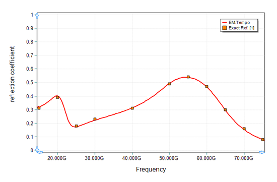 Figure 15: Magnitude of the reflection coefficient of the two-pole Lorentz medium. Solid line: results computed by EM.Tempo, symbols: data presented by Ref. [1]. |
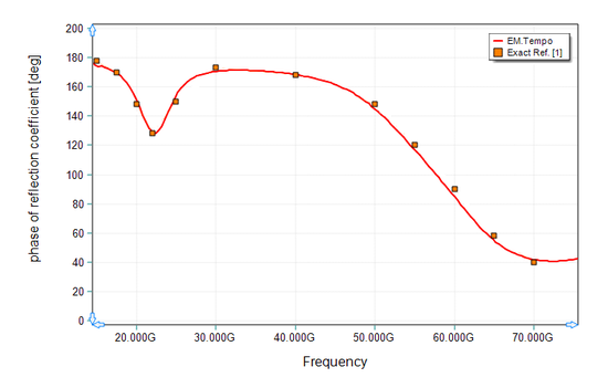 Figure 16: Phase of the reflection coefficient of the two-pole Lorentz medium. Solid line: results computed by EM.Tempo, symbols: data presented by Ref. [1]. |
References
[1] K.S. Kunz and R.J. Luebbers, The Finite Difference Time Domain Method for Electromagnetics. CRC Press, 1993.
[2] K. El-Mahgoub, F. Yang, and A. Elsherbeni, Scattering Analysis of Periodic Structures Using Finite-Difference Time-Domain Method. Morgan & Claypool Publishers, 2012.
