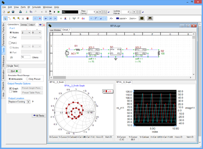
An Overview of RF.Spice
RF.Spice is the “RF Edition” of B2.Spice A/D. In other words, it is an enhanced superset of the B2.Spice A/D application with an extensive library of RF devices that include S-parameter-based multiport networks and a variety of generic and physical transmission line types. You can use RF.Spice to simulate or design distributed analog and mixed-mode circuits at high frequencies.
The major differences between RF.Spice and B2.Spice A/D are:
- The RF.Spice Workshop has an additional RF Menu with a large collection of RF parts.
- The RF.Spice Device Editor has an additional RF Menu with a variety transmission line calculators and designers as well as utilities for importing active and passive S-parameter-based RF device models.
- The RF.Spice parts database is a superset of the B2.Spice A/D parts database.
- The node-locked licenses of the two programs are different.
RF Circuit Analysis
RF circuit analysis, by nature, is an AC analysis that you typically run at high frequencies ranging from tens of Megahertz to tens of Gigahertz. At such high frequencies, the dimensions of your circuit may become comparable in order of magnitude to the wavelength, when wave retardation effects start to appear. In other words, your circuit starts to act like a distributed structure rather than a lumped circuit where signals propagate instantaneously. In the analysis of a low frequency circuit, two nodes that are connected to each other through a wire are assumed to have equal potentials or identical voltages. In RF circuits, however, the connecting wires act as transmission lines, whose lengths play an important role in determining the voltages and currents at different points of the circuit.
At the heart of RF.Spice lie the concepts of RF transmission lines and multiport networks. All the RF devices of RF. Spice can be divided into two groups: devices based on transmission line models, and devices based on multiple networks. As you will see in the later sections of this manual, RF.Spice's transmission line models are based on SPICE's standard LTRA model. Multiport Networks are characterized and modeled based on their frequency-domain scattering (S) parameters.
The S-parameters are tabulated as a function of frequency and interpolated in between the frequency samples. RF.Spice performs an AC analysis of these RF devices by converting their S-parameters to Y-parameters and using them in conjunction with SPICE’s nodal admittance matrix formalism.
The S-parameter-based RF devices of RF.Spice are primarily intended for use in two types of tests:
- AC Frequency Sweep Test
- Network Analysis Test
| |
S-parameter-based RF devices do not work with “Live Simulation” or Transient Test as their models normally contain S-parameters at high frequencies only. |
RF.Spice's simulation engines are the same as the Berkeley SPICE and XSPICE engines of B2.Spice A/D. The high frequency AC analysis is carried out by the same analog and mixed-mode SPICE simulation engine. As a result, you can mix the RF devices in your circuits with all the other analog and mixed-mode devices of B2.Spice A/D. You can also mix transmission-line-type RF devices with digital parts and perform mixed-mode time domain simulations.
From a simulation point of view, an RF circuit is made up of a collection of multiport networks that are interconnected via RF transmission lines. If the input of your circuit is connected to a source and its output is connected to a load, then you can compute all the voltages and currents at all the external or internal ports of the circuit (i.e. at the various circuit nodes). Or you can calculate the port characteristics of the overall network by designating input and output ports to your RF circuit.
Limitations of RF.Spice
The RF circuit analysis performed by RF.Spice is based on the assumption that your distributed RF circuit can be modeled as an interconnected network of multiport devices and transmission line segments and components. This means that all the coupling or crosstalk effects must have been captured by the S-parameter-based models of devices or by the transmission line and discontinuity models used by RF.Spice. Most of these models work satisfactorily at lower frequencies up to several Gigahertz. At these frequencies, a quasi-static regime may be able to represent the physics of your RF circuit to a good level of accuracy. In the quasi-static regime, the different parts of your circuits can be treated as multiport devices or components that are governed by Kirchhoff circuit laws.
As the frequency increases, more complex wave radiation and propagation effects start to appear and affect the performance of your circuit. At much higher frequencies and in the millimeter wave region of the spectrum, the coupling between adjacent transmission lines may no longer be neglected. In such cases, a full-wave electromagnetic analysis of portions of the circuit might become inevitable. This might be especially true for junction areas and vertical interconnects that join transmission line traces on two sides of a board and across different substrate layers. For accurate analysis of structures of this type you need a full-wave electromagnetic (EM) modeling tool. EM.Cube is a modular suite of EM simulation tools for this very purpose. Among its computational modules are time domain full-wave simulators like EM.Tempo based on the Finite Different Time Domain (FDTD) method as well as frequency domain full-wave simulators like EM.Picasso and EM.Libera based on different variations of the Method of Moments (MoM).
