|
|
| (141 intermediate revisions by 2 users not shown) |
| Line 1: |
Line 1: |
| − | '''Welcome to EMAGWARE Wiki!''' | + | '''Welcome to EMAGTECH Wiki Gateway!''' |
| | | | |
| − | [[File:splash-emcube.jpg|thumb|link=EM.Cube|400px]]
| + | <strong><font color="#707983" size="3">Introducing <br /></font></strong> |
| | + | <strong><font color="#07417e" size="4">Unified Modeling, Characterization & Measurement Tools<br /></font></strong> |
| | + | <strong><font color="#07417e" size="4">For RF Circuits, Systems & Electromagnetic Structures</font></strong> |
| | | | |
| − | EMAGWARE is the software division of EMAG Technologies Inc. EMAGWARE currently offers two families of simulation and design software products:
| + | <table> |
| | + | <tr> |
| | + | <td> |
| | + | {|class="wikitable" |
| | + | |- |
| | + | ! [https://www.emagtech.com/wiki/index.php?title=EM.Cube EM.Cube] |
| | + | |- |
| | + | |[[File:emcubePAGE.png |250px | link=https://www.emagtech.com/wiki/index.php?title=EM.Cube]] |
| | + | |- |
| | + | ! [[RF.Spice A/D | RF.Spice A/D]] & [[RF.Spice A/D | B2.Spice A/D]] |
| | + | |- |
| | + | | [[File:RfspicePAGE New.png |250px | link=RF.Spice A/D | RF.Spice A/D]] |
| | + | |- |
| | + | |- |
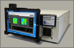
| | + | ! [[NeoScan | NeoScan]] |
| | + | |- |
| | + | | [[File:NeoScan_Product.png |250px | link=NeoScan | NeoScan ]] |
| | + | |- |
| | + | |} |
| | + | </td> |
| | + | </tr> |
| | + | </table> |
| | | | |
| − | * [[EM.Cube | EM.Cube]]
| + | EMAG Technologies Inc. offers three exciting families of software and hardware products for RF, electronics and electrical engineers, including electronic design automation (EDA) tools and RF test and measurement systems. Learn more about each product by clicking on the respective link and access a wealth of documentation, tutorials and videos. |
| − | | + | |
| − | * [[B2.Spice_A/D | B2.Spice A/D]]
| + | |
| − | | + | |
| − | | + | |
| − | [[EM.Cube]] is a modular software environment for the modeling and analysis of RF system engineering problems, featuring seven different electromagnetic simulation engines. [[B2.Spice A/D]] is a comprehensive software tool for analysis and design of analog, digital and mixed-mode electronic circuits, featuring an intuitive but powerful schematic editor and a versatile device editor preloaded with thousands of passive and active devices.
| + | |
| − | | + | |
| − | | + | |
| − | == EM.Cube Documentation ==
| + | |
| − | | + | |
| − | Below are some links to help you get started using [[EM.Cube]]. Each article listed below contains a wealth of information about a particular module, as well as technical information about the numerical techniques used by the underlying simulation engines.
| + | |
| − | * [[Getting_Started_with_EM.CUBE|EM.CUBE: Getting Started]]
| + | |
| − | * [[CubeCAD|CubeCAD: 3D CAD Modeling]]
| + | |
| − | * [[EM.Tempo|EM.Tempo: FDTD Module]]
| + | |
| − | * [[EM.Picasso|EM.Picasso: Planar Module]]
| + | |
| − | * [[EM.Libera|EM.Libera: MoM3D Module]]
| + | |
| − | * [[EM.Illumina|EM.Illumina: Physical Optics Module]]
| + | |
| − | * [[EM.Terrano|EM.Terrano: Propagation Module]]
| + | |
| − | * [[EM.Ferma|EM.Ferma: Static Module]]
| + | |
| − | * [[Hybrid Modeling using Multiple Simulation Engines|Hybrid Modeling]]
| + | |
| − | * [[Data Visualization and Processing]]
| + | |
| − | * [[Parametric Modeling, Sweep & Optimization]]
| + | |
| − | | + | |
| − | | + | |
| − | == EM.Cube Tutorial ==
| + | |
| − | | + | |
| − | Each tutorial lesson listed below walks you through the basic features of one of [[EM.Cube]]'s computational modules.
| + | |
| − | | + | |
| − | * [[FDTDLesson1| FDTD Tutorial Lesson 1 : Analyzing a Center-Fed Resonant Dipole Antenna]]
| + | |
| − | * [[FDTDLesson2| FDTD Tutorial Lesson 2 : Analyzing Scattering from a Sphere]]
| + | |
| − | * [[FDTDLesson3| FDTD Tutorial Lesson 3 : Modeling A Probe-Fed Microstrip Patch Antenna]]
| + | |
| − | * [[FDTDLesson4| FDTD Tutorial Lesson 4 : Analyzing A Planar Microstrip Filter]]
| + | |
| − | | + | |
| − | | + | |
| − | == B2.Spice A/D Documentation ==
| + | |
| − | | + | |
| − | [[File:B2BIG.png|thumb|link=http://www.emagtech.com/|500px]]
| + | |
| − | | + | |
| − | Below are some links to help you get started using [[B2.Spice A/D]].
| + | |
| − | | + | |
| − | * [[B2_intro| B2.Spice A/D: Getting Started]]
| + | |
| − | * [[B2_overview| An Overview of B2.Spice A/D Workshop]]
| + | |
| − | * [[B2_schematic| Working with the Schematic Editor]]
| + | |
| − | * [[B2_analog | Analog and Mixed-Mode Circuit Simulation]]
| + | |
| − | * [[B2_digital | Digital Circuit Simulation]]
| + | |
| − | * [[B2_database | Working with the Parts Database and Device Editor]]
| + | |
| − | * [[B2_symbol | Working with Symbol Editor]]
| + | |
| − | * [[B2_other | Working with Other Applications]]
| + | |
| − | | + | |
| − | | + | |
| − | == B2.Spice A/D Tutorial ==
| + | |
| − | | + | |
| − | Below are some links to help you get started using [[B2.Spice A/D]]. Each tutorial lesson listed below walks you through the basic features of [[B2.Spice A/D]] covering many different topics. Lessons 1-4 teach you how to set up simple analog and digital circuits, perform various tests and live simulations and visualize the simulation results. In Lessons 5 and 6, you will learn how to create new parts, devices, simulation models and symbols using B2.Spice's versatile Device Editor.
| + | |
| − | | + | |
| − | * [[B2_Tutorial1| Tutorial Lesson 1 : A Simple Analog Voltage Divider Circuit]]
| + | |
| − | * [[B2_Tutorial2| Tutorial Lesson 2 : Time and Frequency Analysis of an RLC Filter]]
| + | |
| − | * [[B2_Tutorial3| Tutorial Lesson 3 : Analyzing an RTL Inverter]]
| + | |
| − | * [[B2_Tutorial4| Tutorial Lesson 4 : Building a Digital Three-Input And Function]]
| + | |
| − | * [[B2_Tutorial6| Tutorial Lesson 5 : Creating a New Part from Your Circuit]]
| + | |
| − | * [[B2_Tutorial5| Tutorial Lesson 6 : Creating a Parameterized Subcircuit Part]]
| + | |
| − | | + | |
| − | | + | |
| − | == Featured Article ==
| + | |
| − | {{Featured|{{:Hybrid Modeling using Multiple Simulation Engines|[[Hybrid Modeling]]}}
| + | |
| − | Read more: [[Hybrid Modeling using Multiple Simulation Engines|Hybrid Modeling]]}}
| + | |
| | | | |
| | | | |
| Line 75: |
Line 34: |
| | title=Most Popular Articles | | title=Most Popular Articles |
| | type=hot | | type=hot |
| − | count=8
| |
| − | </DynamicArticleList>
| |
| − |
| |
| − | <DynamicArticleList>
| |
| − | title=Newest Articles
| |
| − | type=new
| |
| | count=8 | | count=8 |
| | </DynamicArticleList> | | </DynamicArticleList> |
EMAG Technologies Inc. offers three exciting families of software and hardware products for RF, electronics and electrical engineers, including electronic design automation (EDA) tools and RF test and measurement systems. Learn more about each product by clicking on the respective link and access a wealth of documentation, tutorials and videos.