Glossary of EM.Cube's Simulation-Related Functions & Operations
Contents
- 1 Project Units
- 2 Frequency Settings
- 3 Materials
- 4 Domain Settings
- 5 Boundary Conditions
- 6 Mesh Generator
- 7 Mesh Settings
- 8 EM.Cube Mesh Types
- 9 Working with EM.Cube's Mesh Generators
- 10 Generating & Viewing the Mesh
- 11 Customizing the Mesh
- 12 Adaptive Yee Mesh
- 13 Adding Fixed Grid Points to the Adaptive Yee Mesh
- 14 Profiling the Brick Mesh
- 15 The FDTD Grid Coordinate System (GCS)
- 16 Fixed-Cell Brick Mesh
- 17 General Rules of EM.Cube's Surface Mesh Generators
- 18 Triangular Surface Mesh
- 19 Facet Mesh
- 20 Wireframe Mesh
- 21 Hybrid Planar Mesh
- 22 Locking the Mesh Density of Object Groups
- 23 Functions
- 24 Variables
- 25 Models
- 26 Custom Output
- 27 Objectives
- 28 Data Manager
- 29 Generate Input Files
- 30 Simulation Engine Settings
- 31 3D Data Generator
- 32 Save Data As
- 33 Delete All Data Files
- 34 Delete All Visualization Data
- 35 Update All Visualization Data
- 36 EM.Grid
- 37 Windows Calculator
- 38 Simulation Run
Project Units
MENU: Simulate → Project Units...
KEYBOARD SHORTCUT: Ctrl+U
FUNCTION: Sets the geometrical units of the project
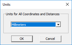
NOTES, SPECIAL CASES OR EXCEPTIONS: You can also access the Units dialog by double-clicking on the units box in the Status Bar. The default unit of a new project is millimeters. The other available options are microns, centimeters, meters, kilometers, mils, inches, feet and miles.
PYTHON COMMAND: set_units(units)
Frequency Settings
MENU: Simulate → Frequency Settings...
KEYBOARD SHORTCUT: Ctrl+F
FUNCTION: Sets the center frequency and bandwidth of the project
NOTES, SPECIAL CASES OR EXCEPTIONS: You can also access the Frequency Settings dialog by double-clicking on the frequency box in the Status Bar. The default units of frequency and bandwidth are GHz. The other available options are Hz, kHz, MHz and THz. "fc" is a reserved project variable for its center frequency and "bw" is a a reserved project variable for its bandwidth. Both fc and bw must be expressed in Hz.
PYTHON COMMAND:
set_frequency(value)
set_bandwidth(value)
Materials
MENU: Simulate → Materials...
KEYBOARD SHORTCUT: Ctrl+T
FUNCTION: Opens EM.Cube's materials list
PYTHON COMMAND: None
EM.Cube provides a preloaded database of popular and widely used materials. You can view the various material entries and their constitutive parameter values. You can also type in the first letter of a material to find it. For example, typing V selects Vacuum in the list.
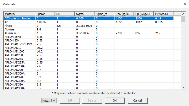 EM.Cube's Materials List. |
Domain Settings
MENU: Simulate → Computational Domain → Domain Settings...
KEYBOARD SHORTCUT: Ctrl+A
FUNCTION: Sets the type & parameters of the computational domain
PYTHON COMMAND:
set_domain_offset(dxn_offset,dxp_offset,dyn_offset,dyp_offset,dzn_offset,dzp_offset)
set_domain_offset_lambda(dxn_offset,dxp_offset,dyn_offset,dyp_offset,dzn_offset,dzp_offset)
Boundary Conditions
MENU: Simulate → Computational Domain → Boundary Conditions...
KEYBOARD SHORTCUT: None
FUNCTION: Sets the type of boundary conditions on the faces of the computational domain in EM.Tempo & EM.Ferma
PYTHON COMMAND: set_boundary_conditions(xn_type,xp_type,yn_type,yp_type,zn_type,zp_type)
Mesh Generator
MENU: Simulate → Discretization → Show Mesh...
KEYBOARD SHORTCUT: Ctrl+M
FUNCTION: Generates and displays the mesh of the physical structure in the current EM.Cube module
PYTHON COMMAND: mesh()
Mesh Settings
MENU: Simulate → Discretization → Mesh Settings...
KEYBOARD SHORTCUT: Ctrl+G
FUNCTION: Sets the density or resolution of the mesh and other related parameters
PYTHON COMMAND:
cubecad_mesh_settings(cell_size,angle_tol)
emtempo_mesh_settings(cells_per_lambda,ratio_contour,ratio_thin,ratio_abs)
emterrano_mesh_settings(edge_length,angle_tol)
emillumina_mesh_settings(cells_per_lambda)
emferma_mesh_settings(cell_size_x,cell_size_y,cell_size_z)
empicasso_mesh_settings(cells_per_lambda)
emlibera_mesh_settings(cells_per_lambda)
EM.Cube Mesh Types
EM.Cube's computational modules use a number of different mesh generation schemes to discretize your physical structure. These include linear, surface and volume mesh generators.
| Mesh Generator | Mesh Type | Supporting Module(s) |
|---|---|---|
| Adaptive Yee Mesh | Volume Mesh | EM.Tempo |
| Fixed-Cell Brick Mesh | Volume Mesh | EM.Tempo, EM.Ferma |
| Triangular Surface Mesh | Surface Mesh | EM.Illumina, EM.Libera, EM.Picasso, EM.Terrano |
| Facet Mesh | Surface Mesh | EM.Terrano |
| Wireframe Mesh | Linear Mesh | EM.Libera |
| Hybrid Planar Mesh | Surface Mesh | EM.Picasso |
The objects of your physical structure are discretized based on a specified mesh density. The default mesh densities of EM.Tempo, EM.Picasso, EM.Libera and EM.Illumina are expressed as the number of cells per effective wavelength. Therefore, the resolution of the default mesh in these modules are frequency-dependent. You can also define the mesh resolution using a fixed cell size or fixed edge length specified in project units. The mesh density of EM.Terrano is always expressed in terms of cell edge length. The mesh resolution of EM.Ferma is always specified as the fixed cell size. All of EM.Cube's computational modules have default mesh settings that usually work well for most simulations.
The accuracy of the numerical solution of an electromagnet problem depends greatly on the quality and resolution of the generated mesh. As a rule of thumb, a mesh density of about 10-30 cells per effective wavelength usually yields satisfactory results. Yet, for structures with lots of fine geometrical details or for highly resonant structures, higher mesh densities may be required. Also, the particular simulation data that you seek in a project also influence your choice of mesh resolution. For example, far field characteristics like radiation patterns are less sensitive to the mesh density than the near-field distributions on a structure with a highly irregular shape and a rugged boundary.
Working with EM.Cube's Mesh Generators
The mesh generation process in EM.Cube typically involves the following steps:
- Setting the mesh properties.
- Generating the mesh.
- Verifying the integrity of the mesh.
- Refining the mesh.
All the mesh generators of EM.Cube's individual computational modules have default settings, which produce a reasonably fine discretization of your physical structure. The most important mesh parameter is the mesh resolution. This can be expressed either as a global mesh density, i.e. the number of cells per wavelength, or by a cell size or maximum cell edge length. Many of EM.Cube mesh types can be customized at the local level of object groups or even at the level of individual objects.
Generating & Viewing the Mesh
MENU:
Simulate → Discretization → Show Mesh
Simulate → Discretization → Regenerate Mesh
KEYBOARD SHORTCUT: Ctrl+M
TO GENERATE AND VIEW A MESH:
- Click the Show Mesh
 button of the Simulate Toolbar.
- EM.Cube's "Mesh View" mode is enabled, and a mesh of your physical structure in the currently active EM.Cube module appears in the project workspace.
- In the "Mesh View" mode, you can perform view operations like rotate view, pan or zoom, but you cannot create new objects or edit existing ones.
- To exit the mesh view mode, press the keyboard's Esc key or click the Show Mesh
 button once again.
PYTHON COMMAND: mesh()
NOTES, SPECIAL CASES OR EXCEPTIONS: Once a mesh is generated, it stays in the memory until the structure is changed or the mesh density or other settings are modified. Every time you view mesh, the one in the memory is displayed. You can force EM.Cube to create a new mesh from the ground up by selecting the menu item Simulate → Discretization → Regenerate Mesh or by right clicking on the Mesh item in the "Discretization" section of the navigation tree and selecting Regenerate from the contextual menu.
Customizing the Mesh
MENU: Simulate → Discretization → Mesh Settings...
KEYBOARD SHORTCUT: Ctrl+G
TO CUSTOMIZE A MESH:
- Click the Mesh Settings
 button of the Simulate Toolbar.
- The Mesh Settings dialog of the currently c=active EM.Cube module opens up.
- From the Host drop-down list, select a line object. Note that only line parallel to one of the three principal axes are listed.
- By default, the lumped source is placed at the midpoint of the host line object. You can modify the Offset parameter, which is measured from the start point of the line and is always positive.
- Click the OK button of the dialog to return to the project workspace.
You can change the mesh algorithm from the dropdown list labeled Mesh Type if there is more than one option. You can also enter a different value for Mesh Density in cells per effective wavelength (λeff). For each value of mesh density, the dialog also shows the average "Cell Edge Length" in the free space.
PYTHON COMMAND: mesh()
cubecad_mesh_settings(cell_size,angle_tol)
emtempo_mesh_settings(cells_per_lambda,ratio_contour,ratio_thin,ratio_abs)
emterrano_mesh_settings(edge_length,angle_tol)
emillumina_mesh_settings(cells_per_lambda)
emferma_mesh_settings(cell_size_x,cell_size_y,cell_size_z)
empicasso_mesh_settings(cells_per_lambda)
emlibera_mesh_settings(cells_per_lambda)
Adaptive Yee Mesh
MODULE: EM.Tempo
FUNCTION: Generates a Yee brick mesh that adapts to the fine geometric details and material composition of the physical structure
PYTHON COMMAND: emtempo_mesh_settings(cells_per_lambda,ratio_contour,ratio_thin,ratio_abs)
ADAPTIVE YEE MESH PARAMETERS
| Parameter Name | Value Type | Units | Default Value | Notes |
|---|---|---|---|---|
| minimum mesh density | real numeric | cells/lambda_eff | 20 | effective wavelength in the material medium |
| minimum grid spacing for geometric contours | real numeric | - | 0.4 | as a fraction of maximum grid spacing in free space |
| minimum grid spacing at thin or narrow regions | real numeric | - | 0.4 | as a fraction of maximum grid spacing in free space |
| absolute minimum grid spacing | real numeric | - | 0.15 | as a fraction of maximum grid spacing in free space |
| maximum adjacent cell size ratio | real numeric | - | 1.3 | controls gradual grid transitions |
| curved edge angle tolerance | real numeric | degrees | 15 | controls the initial tessellation of the physical structure |
Adding Fixed Grid Points to the Adaptive Yee Mesh
Adding fixed grid points to an FDTD mesh increases its resolution locally. Each fixed grid point adds three grid lines along the three principal axes passing through that point. You can add as many fixed grid points as you desire and create dense meshes at certain regions. Fixed grid points appear as grey points in the project workspace. To insert a new fixed grid point, follow these steps:
- Open the Fixed Grid Points Dialog by selecting Menu > Simulate > Discretization > Fixed Grid Points... or by right-clicking on the FDTD Mesh item of the navigation tree and selecting Fixed Grid Points Settings...
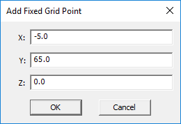
- Click the Add/Edit button to open the "Add Fixed Grid Point" dialog.
- Enter the (X, Y, Z) coordinates of the new fixed point in the coordinate boxes and click the OK button.
- To modify the coordinates of an existing fixed grid point, select it from the table and click the Add/Edit button.
- You can also remove a fix grid point from the FDTD mesh using the Delete button.
According to the Courant-Friedrichs-Levy (CFL) stability criterion, the FDTD time step is determined by the smallest cell size in your FDTD mesh. Occasionally, FDTD Module's adaptive mesh generator may create extremely tiny grid cells that would result in extremely small time steps. This would then translate into a very long computation time. EM.Cube offers the "Regular" FDTD mesh generator, which is a simplified version of the adaptive mesh generator. In a regular FDTD mesh, the grid cell sizes stay rather the same in objects of the same material composition. The mesh resolution increases in materials of higher permittivity and/or permeability based on the effective wavelength in exactly the same way as the adaptive mesh.
Profiling the Brick Mesh
A volumetric brick mesh is overwhelming for visualization in the 3D space. For this reason, EM.Cube's mesh view shows only the outline of the cells on exterior surface of the (staircased) meshed objects. The mesh grid planes provide a 2D profile of the mesh cells along the principal coordinate planes. To display a mesh grid plane, select Menu > Simulate > Discretization > Grid Planes > and pick one of the three options: XY Plane, YZ Plane or ZX Plane. You may also right click on one of the XY Plane, YZ Plane or ZX Plane items in the Discretization section of the navigation tree and select Show from the contextual menu.
While a mesh grid plane is visible, you can move it back and forth between the two boundary planes at the two opposite sides of the computational domain. You can do this in one of the following four ways:
- Using the keyboard's Page Up PgUp key and Page Down PgDn key.
- By selecting Menu > Simulate > Discretization > Grid Planes > Increment Grid or Decrement Grid.
- By right clicking on one of the XY Plane, YZ Plane or ZX Plane items in the Discretization section of the navigation tree and selecting Increment Grid or Decrement Grid from the contextual menu.
- Using the keyboard shortcut > or <.
As you “step through” or profile the mesh grid, you can see how the structure is discretized along internal planes of the computational domain.
The FDTD Grid Coordinate System (GCS)
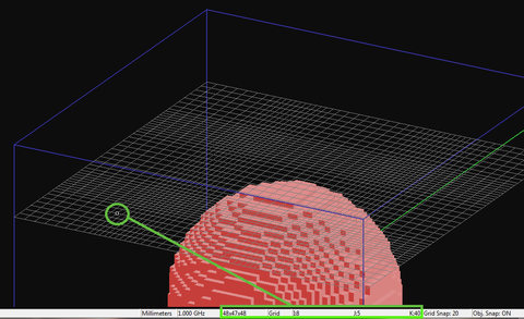
When your physical structure is discretized using the brick mesh generator, a second coordinate system becomes available to you. The mesh grid coordinate system allows you to specify any location in the computational domain in terms of node indices on the mesh grid. EM.Cube displays the total number of mesh grid lines of the simulation domain (Nx × Ny × Nz) along the three principal axes on the Status Bar. Therefore, the number of cells in each direction is one less than the number of grid lines, i.e. (Nx-1)× (Ny-1) × (Nz-1). The lower left front corner of the domain box (Xmin, Ymin, Zmin) becomes the origin of the mesh grid coordinate system (I = 0, J = 0, K = 0). The upper right back corner of the domain box (Xmax, Ymax, Zmax) therefore becomes (I = Nx-1, J = Ny-1, K = Nz-1).
EM.Cube allows you to navigate through the mesh grid and evaluate the grid points individually. Every time you display one of the three mesh grid planes, the "Grid Coordinate System (GCS)" is automatically activated. On the Status Bar, you will see ![]() instead of the default
instead of the default ![]() . This means that the current coordinates reported on Status Bar are now expressed in grid coordinate system. The current grid point is displayed by a small white circle on the current mesh grid plane, and it always starts from (I = 0, J = 0, K = 0). Using the keyboard's Arrow Keys, you can move the white circle through the mesh grid plane and read the current node's (I, J, K) indices on the status bar. You can switch back to the "World Coordinate System (WCS)" or change to the "Domain Coordinate System" by double-clicking the status bar box that shows the current coordinate system and cycling through the three options. The domain coordinate system is one that establishes its origin at the lower left front corner of the computational domain and measure distances in project unit just like the WCS.
. This means that the current coordinates reported on Status Bar are now expressed in grid coordinate system. The current grid point is displayed by a small white circle on the current mesh grid plane, and it always starts from (I = 0, J = 0, K = 0). Using the keyboard's Arrow Keys, you can move the white circle through the mesh grid plane and read the current node's (I, J, K) indices on the status bar. You can switch back to the "World Coordinate System (WCS)" or change to the "Domain Coordinate System" by double-clicking the status bar box that shows the current coordinate system and cycling through the three options. The domain coordinate system is one that establishes its origin at the lower left front corner of the computational domain and measure distances in project unit just like the WCS.
Fixed-Cell Brick Mesh
FUNCTION: Generates a uniform 3D brick mesh with specified cell dimensions along the three principal axes to which the physical structure is adapted
PYTHON COMMAND: emferma_mesh_settings(cell_size_x,cell_size_y,cell_size_z)
FIXED-CELL BRICK MESH PARAMETERS
| Parameter Name | Value Type | Units | Default Value | Notes |
|---|---|---|---|---|
| cell_size_x | real numeric | project units | 1 | - |
| cell_size_y | real numeric | project units | 1 | - |
| cell_size_z | real numeric | project units | 1 | - |
General Rules of EM.Cube's Surface Mesh Generators
- The surface mesh generator merges all the objects that belong to the same group in the navigation Tree using the Boolean Union operation before meshing. The union operation is carried out temporarily and solely for the purpose of mesh generation.
- As a result of the Boolean union operation, all the overlapping objects are transformed into a single consolidated object leading to a contiguous and consistent mesh in the transition and junction areas between connected objects.
- In general, objects of the same CAD category can be "unioned". For example, surface objects can be merged together, and so can solid objects. However, a surface object and a solid in general do not merge.
- In general, objects that belong to different groups on the navigation tree are not merged during mesh generation even if they have the same material composition and physically overlap.
- Only EM.Libera's surface mesh generator creates a special junction mesh between overlapping objects that have different material compositions.
- All Polymesh objects as well as EM.Terrano's terrain objects are considered already discretized and are not re-meshed once again by the surface mesh generator.
Triangular Surface Mesh
MODULE: EM.Illumina, EM.Libera, EM.Picasso
FUNCTION: Generates a highly regular triangular surface mesh based on a mesh density expressed in cells per effective wavelength
PYTHON COMMAND(S):
emillumina_mesh_settings(cells_per_lambda)
emlibera_mesh_settings(cells_per_lambda)
TRIANGULAR SURFACE MESH PARAMETERS
| Parameter Name | Value Type | Units | Default Value | Notes |
|---|---|---|---|---|
| density | real numeric | cells/lambda_eff | 10 | determines the mesh resolution as a function of operating frequency |
| curved edge angle tolerance | real numeric | degrees | 15 | controls the initial tessellation of the physical structure |
| chord height | real numeric | project units | 0 | controls the initial tessellation of the physical structure |
| maximum edge segment length | real numeric | project units | 0 | controls the initial tessellation of the physical structure |
Facet Mesh
MODULE: EM.Terrano
FUNCTION: Generates a triangular surface mesh based on a specified edge length
PYTHON COMMAND: emterrano_mesh_settings(edge_length,angle_tol)
FACET MESH PARAMETERS
| Parameter Name | Value Type | Units | Default Value | Notes |
|---|---|---|---|---|
| cell edge length | real numeric | project units | 100 | determines the mesh resolution |
| curved edge angle tolerance | real numeric | degrees | 45 | controls the initial tessellation of the physical structure |
| chord height | real numeric | project units | 0 | controls the initial tessellation of the physical structure |
| maximum edge segment length | real numeric | project units | 0 | controls the initial tessellation of the physical structure |
Wireframe Mesh
MODULE: EM.Libera
FUNCTION: Generates a polygonized mesh of curve objects and a regular triangular mesh of surface and solid objects
PYTHON COMMAND: emlibera_mesh_settings(cells_per_lambda)
WIREFRAME MESH PARAMETERS
| Parameter Name | Value Type | Units | Default Value | Notes |
|---|---|---|---|---|
| density | real numeric | cells/lambda_eff | 10 | determines the mesh resolution as a function of operating frequency |
| curved edge angle tolerance | real numeric | degrees | 15 | controls the initial tessellation of the physical structure |
| chord height | real numeric | project units | 0 | controls the initial tessellation of the physical structure |
| maximum edge segment length | real numeric | project units | 0 | controls the initial tessellation of the physical structure |
Hybrid Planar Mesh
MODULE: EM.Picasso
FUNCTION: Generates a surface mesh of planar structures containing mixed rectangular and triangular cells
PYTHON COMMAND: empicasso_mesh_settings(cells_per_lambda)
HYBRID PLANAR MESH PARAMETERS
| Parameter Name | Value Type | Units | Default Value | Notes |
|---|---|---|---|---|
| mesh density | real numeric | cells/lambda_eff | 20 | determines the mesh resolution as a function of operating frequency |
| maximum angle for defective cell removal | real numeric | degrees | 5 | eliminates narrow cells with angles smaller than this value |
Locking the Mesh Density of Object Groups
The mesh density is a global parameter. It controls the resolution of the mesh of all the geometric objects in your project workspace. Some of EM.Cube's modules like EM.Tempo and EM.Picasso refine the mesh in material regions or on certain traces based on the material properties of those regions. This leads to a non-uniform mesh from region to region, e.g., from a free-space region to a material block.
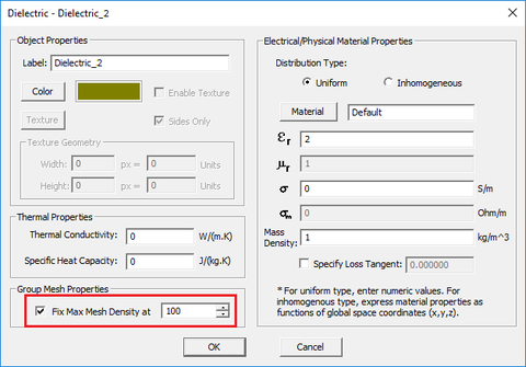
Another way of local mesh control is to lock the mesh density of certain object groups. In that case, the locked mesh density takes precedence over the global mesh density. Locking the mesh can be useful for isolated object groups that may require a higher (or lower) mesh resolution. You can lock the local mesh density by accessing the property dialog of any object group or material group from the navigation tree. Check the box labeled Fix Max Mesh Density and enter a value for the mesh density different than the global mesh density of your project.
Functions
MENU: Simulate → Functions...
KEYBOARD SHORTCUT: Ctrl+I
FUNCTION: Opens the list of standard, preloaded and EM.Cube Python functions
PYTHON COMMAND: None
Variables
MENU: Simulate → Variables...
KEYBOARD SHORTCUT: Ctrl+B
FUNCTION: Opens the list of constants, default project variables and available user-defined variables
PYTHON COMMAND: None
Models
MENU: Simulate → Python Models & Scripts...
KEYBOARD SHORTCUT: Ctrl+L
FUNCTION: Opens the list of the preloaded and currently available user-defined Python models and scripts
PYTHON COMMAND: None
Custom Output
MENU: Simulate → Cutom Output...
KEYBOARD SHORTCUT: Ctrl+K
FUNCTION: Opens the list of the currently available user-defined custom Outputs
PYTHON COMMAND: None
Objectives
MENU: Simulate → Objective...
KEYBOARD SHORTCUT: Ctrl+J
FUNCTION: Opens the list of the currently available user-defined design objectives
PYTHON COMMAND: None
Data Manager
MENU: Simulate → Data Manager...
KEYBOARD SHORTCUT: Ctrl+D
FUNCTION: Opens EM.Cube's Data Manager
PYTHON COMMAND: None
Generate Input Files
ICON: None
MENU: Simulate → Generate Input Files...
KEYBOARD SHORTCUT: None
FUNCTION: Generates all the necessary input files to run a simulation in one of EM.Cube's computational modules
PYTHON COMMAND: None
Simulation Engine Settings
ICON: None
MENU: Simulate → Simulation Engine Settings...
KEYBOARD SHORTCUT: Ctrl+Shift+N
FUNCTION: Sets the numerical user-accessible simulation parameters in one of EM.Cube's computational modules
PYTHON COMMAND:
emtempo_engine_settings(engine,power_threshhold,max_timesteps)
emterrano_engine_settings(bounce_count,do_edge_diffraction,angular_resolution,ray_threshhold)
emillumina_engine_settings(engine,is_fixed_iteration,error_tol,max_iterations)
emferma_engine_settings(matrix_solver,error_tol,max_iterations)
empicasso_engine_settings(matrix_solver,error_tol,max_iterations)
emlibera_engine_settings_smom(matrix_solver,error_tol,max_iterations,ncpus,formulation,alpha)
emlibera_engine_settings_wmom(matrix_solver,error_tol,max_iterations)
3D Data Generator
ICON: None
MENU: Simulate → 3D Data Generator...
KEYBOARD SHORTCUT: Ctrl+Shift+D
FUNCTION: Opens EM.Cube's 3D Data Generator
PYTHON COMMAND: None
Save Data As
ICON: None
MENU: Simulate → Save Data As...
KEYBOARD SHORTCUT: None
FUNCTION: Saves a project's data files in a specified subfolder other than the current project folder
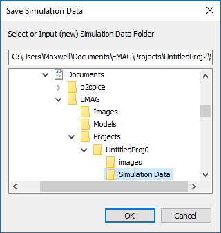
NOTES, SPECIAL CASES OR EXCEPTIONS: This operation opens up the "Save Data" dialog with the default file path set to a subfolder named "Simulation Data" under your current project folder. You can choose the default subfolder name and location or change the name or browse to another location on your hard drive. it is important to keep in mind that before every simulation, EM.Cube deletes all the data files in the current project folder. In order to preserve your simulation data, you have to save them in a different folder other than the project folder.
PYTHON COMMAND: None
Delete All Data Files
ICON: None
MENU: Simulate → Delete All Data Files
KEYBOARD SHORTCUT: None
FUNCTION: Deletes all the data files in the current project folder
PYTHON COMMAND: None
Delete All Visualization Data
ICON: None
MENU: Simulate → Delete All Visualization Data
KEYBOARD SHORTCUT: None
FUNCTION: Deletes all the visualization data under the "Observables" section of the navigation tree
PYTHON COMMAND: None
Update All Visualization Data
ICON: None
MENU: Simulate → Update All Visualization Data
KEYBOARD SHORTCUT: None
FUNCTION: Reloads all the visualization data under the "Observables" section of the navigation tree from the respective 3D data files in the current project file
NOTES, SPECIAL CASES OR EXCEPTIONS: This operation is particularly useful when the simulation engine resides on another computer (e.g. on a Linux machine) and is run from the command line. At the end of the simulation, you can transfer all the output simulation data files including the 3D data files like ".RAD", ".SEN", ".CUR", "RCS", etc. to your Windows computer for data visualization.
PYTHON COMMAND: None
EM.Grid
ICON: None
MENU: Simulate → EM.Grid...
KEYBOARD SHORTCUT: Ctrl+Shift+G
FUNCTION: Opens EM.Grid for plotting data files
PYTHON COMMAND: plot_file(filename)
Windows Calculator
MENU: Simulate → Windows Calculator...
KEYBOARD SHORTCUT: None
FUNCTION: Opens Windows calculator
PYTHON COMMAND: None
Simulation Run
MENU: Simulate → Run...
KEYBOARD SHORTCUT: Ctrl+R
FUNCTION: Opens the Simulation Run dialog where you can set the simulation engine type & simulation mode and run a new simulation in one of EM.Cube's computational modules
PYTHON COMMAND: run_analysis()
