EM.Terrano Tutorial Lesson 9: A SBR Channel Analysis of An Urban Scene
Contents
What You Will Learn
In this tutorial lesson, you will learn how to perform a SBR Channel Analysis of your propagation scene and examine the individual rays received by each receiver. Then, you will learn how to perform a rotational sweep in order to rotate the radiation pattern of the transmitter(s) and receiver(s) about one of the three principal axes sequentially.
![]() Back to EM.Terrano Tutorial Gateway
Back to EM.Terrano Tutorial Gateway
![]() Download projects related to this tutorial lesson
Download projects related to this tutorial lesson
Getting Started
Open the EM.Cube application and switch to EM.Terrano. If you downloaded the Ann Arbor template project in the tutorial lesson 7, open it again and save it as "EMTerrano_Lesson9". Otherwise, download the template project by clicking this link, and then open the downloaded project. Set the center frequency of the project to 1GHz. The table below summarizes the project parameters:
Use the Basic Link Wizard to create a vertically polarized dipole transmitter and a grid of isotropic receivers. Use the following parameters for the wizard:
| Parameter Name | Default Value | New Value |
|---|---|---|
| area_size | 500 | 850 |
| Tx Location X | 0 | 425 |
| Tx Location Y | 0 | 425 |
| Transmitter Height | 10 | 5 |
| Receiver Height | 1.5 | 1.5 |
| Receiver Spacing | 5 | 10 |
and change the coordinates of the point radiator "RXA" to (0, 0, rx_h) and change the Element Count along the Y direction to 0.9* rx_count. Your Ann Arbor scene should look like the figure the below:
SBR Channel Analysis
Both the SBR Field Solver and the SBR Channel Analyzer perform the same type of simulation but in two different ways. The SBR solver discretizes the scene including all the buildings and terrain, shoots a large number of rays from the transmitters and collects the rays at the receivers. The SBR Channel Analyzer does the same thing using an existing polarimetric ray database that has been previously generated using EM.Terrano's Channel Analyzer. It incorporates the effects of the radiation patterns of the transmit and receive antennas in conjunction with the polarimetric channel characteristics. At the end of a ray tracing simulation, all the polarimetric rays emanating from the transmitter(s) or other sources that are received by the individual receivers are computed, collected, sorted and saved into ASCII data files. From the ray data, the total electric field at the location of receivers as well as the total received power are computed. The individual ray data include the field components of each ray, the ray's elevation and azimuth angles of departure and arrival (departure from the transmitter location and arrival at the receiver location), and time delay of the received ray with respect to the transmitter.
Running an SBR Channel Analyzer
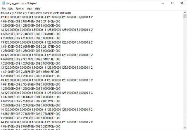
To perform a polarimatric channel characterization of your propagation scene, open EM.Terrano's Run Simulation dialog and select SBR Channel Analyzer from the drop-down list labeled Select Simulation or Solver Type and state a simulation of the "Single-Frequency Analysis" type. At the end of the simulation, a large ray database is generated with two data files called "sbr_channel_matrix.DAT" and "sbr_ray_path.DAT". The former file contains the delay, angles of arrival and departure and complex-valued elements of the channel matrix for all the individual rays that leave each transmitter and arrive at each receiver. The latter file contains the geometric aspects of each ray such as hit point coordinates.
Visualization of the Received Power Coverage Map
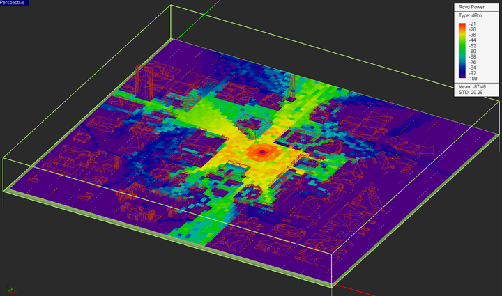
You cannot visualize the coverage map merely by running the SBR Channel Analyzer. The main output data file "sbr_results.RTOUT" is needed for ray visualization. This file contains all the information about individual receivers and the parameters of each ray that is received by each individual receiver. Therefore, after running "SBR Channel Analyzer", you have run Communication Link Solver (Polarimatrix) with a simulation of the "Single-Frequency Analysis" type. Keep in mind that the default transmitter and receivers type are a vertically polarized (Z-directed) half-wave dipole antenna.
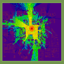
To verify the simulation results, compare the received power coverage map of the Ann Arbor scene with that of the lesson 7 at f = 1GHz.
In this part of this tutorial lesson, you will import the radiation pattern of a Z-directed vertically polarized half-wave dipole for the Transmitter. Open the property dialog of the Point Radiator Set – TXB and import the radiation pattern file "DPL_STD.RAD". Run Communication Link Solver (Polarimatrix) with a simulation of the "Single-Frequency Analysis" type.
Running a Rotational Sweep Simulation of Your Propagation Scene
In the last part of this tutorial lesson, you will perform a rotational sweep simulation of your propagation Scene. You can rotate the 3D radiation patterns of both the transmitters and receivers from the property dialog of the parent transmitter set or receiver set. This is done in advance before a SBR simulation starts. You can define one or more of the rotation angles of a transmitter set or a receiver set as sweep variables and perform a parametric sweep simulation. In that case, the entire scene and all of its buildings are discretized at each simulation run and a complete physical SBR ray tracing simulation is carried out. However, we know that the polarimetric characteristics of the propagation channel are independent of the transmitter or receiver antenna patterns or their rotation angles. A rotational sweep allows you to rotate the radiation pattern of the transmitter(s) about one of the three principal axes sequentially. This is equivalent to the steering of the beam of the transmit antenna either mechanically or electronically. The result of the sweep simulation is a number of received power coverage maps, each corresponding to one of the angular samples. To run a rotational sweep, you must specify the rotation angle.
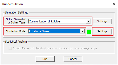
Import the radiation pattern of a linear 5-element vertical dipole array for your transmitter. The name of the radiation pattern file is "Dipole_Array1.RAD". You can download this file by clicking this link. Then, open EM.Terrano's Simulation Run dialog and select Communication Link Solver (Polarimatrix) with Rotational Sweep (COMM Link Solver only) as the simulation mode.
Click on the Settings button next to this drop-down list to open the Rotational Sweep Settings dialog. In the rotational sweep settings dialog, select Z as the rotation axis of Tx and set the values of the start and stop angle to 0 and 360 degrees, respectively, and set the No. of frequency Samples to 12. This will result in a angle step of 30 degrees. Select “No Rotation” for the receivers (Rx Antenna).
You are now ready to run a rotational sweep simulation of your project. Start the sweep and wait until all the 12 individual SBR simulations are completed. Then, visualize the coverage map.


