Difference between revisions of "Glossary of EM.Cube's Wizards"
Kazem Sabet (Talk | contribs) |
Kazem Sabet (Talk | contribs) |
||
| Line 1,180: | Line 1,180: | ||
<td> | <td> | ||
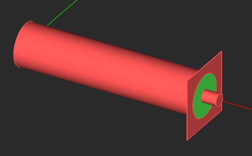
[[Image:wiz_us_ferma.png|thumb|500px|Default 2D microstrip line in EM.Ferma.]] | [[Image:wiz_us_ferma.png|thumb|500px|Default 2D microstrip line in EM.Ferma.]] | ||
| + | </td> | ||
| + | </tr> | ||
| + | </table> | ||
| + | |||
| + | == Microstrip-Fed Patch Wizard == | ||
| + | |||
| + | ICON: [[File:us_patch_icon.png]] | ||
| + | |||
| + | MENU: '''Tools → Antenna Wizards → Microstrip-Fed Patch Antenna''' | ||
| + | |||
| + | MODULE(S): [[EM.Tempo]], [[EM.Picasso]] | ||
| + | |||
| + | FUNCTION: Creates the parameterized geometry of a microstrip-fed rectangular patch antenna in the project workspace | ||
| + | |||
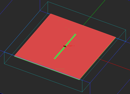
| + | NOTES, SPECIAL CASES OR EXCEPTIONS: The wizard asks you whether you want a microstrip-fed patch antenna with a recessed feed or one with a direct microstrip line junction. In [[EM.Tempo]], the feed line is excited by a microstrip port. In [[EM.Picasso]], the feed line has a scattering wave port. The total dimensions of the square patch are set equal to 0.5 times the effective dielectric wavelength, which can be changed. | ||
| + | |||
| + | |||
| + | PYTHON COMMAND(S): | ||
| + | |||
| + | emag_microstrip_fed_patch_tempo(is_recess,h,er,z0,feed_len,recess_dep,recess_wid,sub_len,sub_wid) | ||
| + | |||
| + | emag_microstrip_fed_patch_picasso(is_recess,h,er,z0,feed_len,recess_dep,recess_wid) | ||
| + | |||
| + | |||
| + | MICROSTRIP-FED PATCH WIZARD PARAMETERS | ||
| + | {| border="0" | ||
| + | |- | ||
| + | | valign="top"| | ||
| + | |- | ||
| + | {| class="wikitable" | ||
| + | |- | ||
| + | ! scope="col"| Parameter Name | ||
| + | ! scope="col"| Value Type | ||
| + | ! scope="col"| Units | ||
| + | ! scope="col"| Default Value | ||
| + | ! scope="col"| Notes | ||
| + | |- | ||
| + | ! scope="row" | is_recess | ||
| + | | Boolean | ||
| + | | - | ||
| + | | True | ||
| + | | Creates a recessed feed vs. a direct microstrip line junction to the patch | ||
| + | |- | ||
| + | ! scope="row" | h | ||
| + | | real numeric | ||
| + | | meter | ||
| + | | 0.0015 | ||
| + | | substrate thickness (height) | ||
| + | |- | ||
| + | ! scope="row" | er | ||
| + | | real numeric | ||
| + | | - | ||
| + | | 2.2 | ||
| + | | substrate relative permittivity | ||
| + | |- | ||
| + | ! scope="row" | z0 | ||
| + | | real numeric | ||
| + | | Ohms | ||
| + | | 50 | ||
| + | | characteristic impedance of the microstrip feed | ||
| + | |- | ||
| + | ! scope="row" | feed_len | ||
| + | | real numeric | ||
| + | | meter | ||
| + | | 0.075 | ||
| + | | length of the microstrip feed line | ||
| + | |- | ||
| + | ! scope="row" | recess_dep | ||
| + | | real numeric | ||
| + | | meter | ||
| + | | 0.015 | ||
| + | | depth of the feed recess | ||
| + | |- | ||
| + | ! scope="row" | recess_wid | ||
| + | | real numeric | ||
| + | | meter | ||
| + | | 0.005 | ||
| + | | width of the recess gaps | ||
| + | |- | ||
| + | ! scope="row" | sub_len | ||
| + | | real numeric | ||
| + | | meter | ||
| + | | 0.3 | ||
| + | | substrate dimension along X (only in [[EM.Tempo]]) | ||
| + | |- | ||
| + | ! scope="row" | sub_wid | ||
| + | | real numeric | ||
| + | | meter | ||
| + | | 0.3 | ||
| + | | substrate dimension along Y (only in [[EM.Tempo]]) | ||
| + | |} | ||
| + | |||
| + | <table> | ||
| + | <tr> | ||
| + | <td> | ||
| + | [[Image:wiz_us_patch_tempo.png|thumb|500px|Default microstrip-fed patch antenna in EM.Tempo.]] | ||
| + | </td> | ||
| + | </tr> | ||
| + | <tr> | ||
| + | <td> | ||
| + | [[Image:wiz_us_patch_picasso.png|thumb|500px|Default microstrip-fed patch antenna in EM.Picasso.]] | ||
| + | </td> | ||
| + | </tr> | ||
| + | <tr> | ||
| + | <td> | ||
| + | [[Image:wiz_us_patch_recess_tempo.png|thumb|500px|Default microstrip-fed patch antenna with a recessed feed in EM.Tempo.]] | ||
| + | </td> | ||
| + | </tr> | ||
| + | <tr> | ||
| + | <td> | ||
| + | [[Image:wiz_us_patch_recess_picasso.png|thumb|500px|Default microstrip-fed patch antenna with a recessed feed in EM.Picasso.]] | ||
</td> | </td> | ||
</tr> | </tr> | ||
| Line 1,426: | Line 1,537: | ||
<td> | <td> | ||
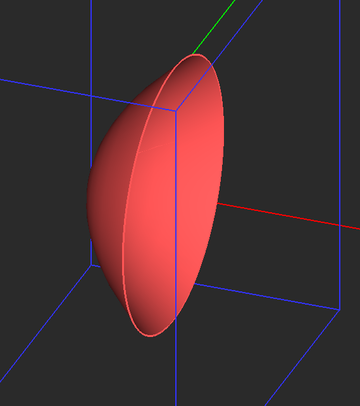
[[Image:wiz_dish_tempo.png|thumb|360px|Default parabolic reflector in EM.Tempo.]] | [[Image:wiz_dish_tempo.png|thumb|360px|Default parabolic reflector in EM.Tempo.]] | ||
| + | </td> | ||
| + | </tr> | ||
| + | </table> | ||
| + | |||
| + | == Particle Cloud Wizard == | ||
| + | |||
| + | ICON: [[File:cloud icon.png]] | ||
| + | |||
| + | MENU: '''Tools → Component Wizards → Particle Cloud''' | ||
| + | |||
| + | MODULE(S): [[Building_Geometrical_Constructions_in_CubeCAD | CubeCAD]], [[EM.Tempo]], [[EM.Illumina]], [[EM.Ferma]], [[EM.Libera]] | ||
| + | |||
| + | FUNCTION: Creates the parameterized geometry of a random cloud of regular polygon particles contained in an ellipsoid region | ||
| + | |||
| + | NOTES, SPECIAL CASES OR EXCEPTIONS: The aperture diameter of the reflector is determined based on the focal and axial lengths of the primitive parabola. | ||
| + | |||
| + | |||
| + | PYTHON COMMAND(S): | ||
| + | |||
| + | emag_particle_cloud(n_sides,side_length,cont_radius_x,cont_radius_y,cont_radius_z,n_elements) | ||
| + | |||
| + | emag_particle_cloud_cad(n_sides,side_length,cont_radius_x,cont_radius_y,cont_radius_z,n_elements) | ||
| + | |||
| + | |||
| + | PARTICLE CLOUD WIZARD PARAMETERS | ||
| + | {| border="0" | ||
| + | |- | ||
| + | | valign="top"| | ||
| + | |- | ||
| + | {| class="wikitable" | ||
| + | |- | ||
| + | ! scope="col"| Parameter Name | ||
| + | ! scope="col"| Value Type | ||
| + | ! scope="col"| Units | ||
| + | ! scope="col"| Default Value | ||
| + | ! scope="col"| Notes | ||
| + | |- | ||
| + | ! scope="row" | n_sides | ||
| + | | integer numeric | ||
| + | | - | ||
| + | | 4 | ||
| + | | number of sides of the regular polygon particle | ||
| + | |- | ||
| + | ! scope="row" | side_length | ||
| + | | real numeric | ||
| + | | project units | ||
| + | | 2 | ||
| + | | side length of the regular polygon particle | ||
| + | |- | ||
| + | ! scope="row" | cont_radius_x | ||
| + | | real numeric | ||
| + | | project units | ||
| + | | 200 | ||
| + | | radius of the ellipsoid container along X | ||
| + | |- | ||
| + | ! scope="row" | cont_radius_y | ||
| + | | real numeric | ||
| + | | project units | ||
| + | | 200 | ||
| + | | radius of the ellipsoid container along Y | ||
| + | |- | ||
| + | ! scope="row" | cont_radius_z | ||
| + | | real numeric | ||
| + | | project units | ||
| + | | 100 | ||
| + | | radius of the ellipsoid container along Z | ||
| + | |- | ||
| + | ! scope="row" | n_elements | ||
| + | | integer numeric | ||
| + | | - | ||
| + | | 100 | ||
| + | | total number of particles | ||
| + | |} | ||
| + | |||
| + | <table> | ||
| + | <tr> | ||
| + | <td> | ||
| + | [[Image:wiz_cloud_tempo.png|thumb|500px|Default particle cloud in EM.Tempo with the ellipsoid container in the freeze state.]] | ||
</td> | </td> | ||
</tr> | </tr> | ||
| Line 1,506: | Line 1,695: | ||
<td> | <td> | ||
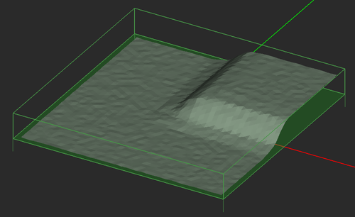
[[Image:wiz_plateau.png|thumb|500px|Default plateau terrain in EM.Terrano.]] | [[Image:wiz_plateau.png|thumb|500px|Default plateau terrain in EM.Terrano.]] | ||
| + | </td> | ||
| + | </tr> | ||
| + | </table> | ||
| + | |||
| + | == Printed Dipole Wizard == | ||
| + | |||
| + | ICON: [[File:print_dpl icon.png]] | ||
| + | |||
| + | MENU: '''Tools → Antenna Wizards → Printed Dipole Antenna''' | ||
| + | |||
| + | MODULE(S): [[EM.Tempo]], [[EM.Picasso]] | ||
| + | |||
| + | FUNCTION: Creates the parameterized geometry of a printed dipole antenna on a dielectric substrate in the project workspace | ||
| + | |||
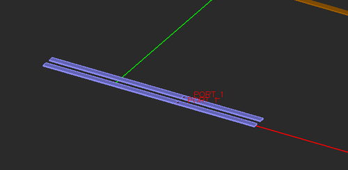
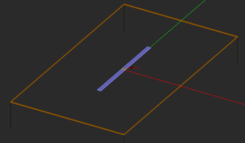
| + | NOTES, SPECIAL CASES OR EXCEPTIONS: In [[EM.Tempo]], the printed dipole consists of two PEC strips fed by a lumped source on a short joining line. In [[EM.Picasso]], the printed dipole is a single PEC strip with a gap source on it. | ||
| + | |||
| + | |||
| + | PYTHON COMMAND(S): | ||
| + | |||
| + | emag_printed_dipole_tempo(h,er,wid,sub_size,has_ground) | ||
| + | |||
| + | emag_printed_dipole_picasso(h,er,wid,has_ground) | ||
| + | |||
| + | |||
| + | PRINTED DIPOLE WIZARD PARAMETERS | ||
| + | {| border="0" | ||
| + | |- | ||
| + | | valign="top"| | ||
| + | |- | ||
| + | {| class="wikitable" | ||
| + | |- | ||
| + | ! scope="col"| Parameter Name | ||
| + | ! scope="col"| Value Type | ||
| + | ! scope="col"| Units | ||
| + | ! scope="col"| Default Value | ||
| + | ! scope="col"| Notes | ||
| + | |- | ||
| + | ! scope="row" | h | ||
| + | | real numeric | ||
| + | | meter | ||
| + | | 0.0015 | ||
| + | | substrate thickness (height) | ||
| + | |- | ||
| + | ! scope="row" | er | ||
| + | | real numeric | ||
| + | | - | ||
| + | | 2.2 | ||
| + | | substrate relative permittivity | ||
| + | |- | ||
| + | ! scope="row" | wid | ||
| + | | real numeric | ||
| + | | meter | ||
| + | | 0.005 | ||
| + | | strip width | ||
| + | |- | ||
| + | ! scope="row" | sub_size | ||
| + | | real numeric | ||
| + | | meter | ||
| + | | 0.15 | ||
| + | | substrate dimensions along X and Y (only in [[EM.Tempo]]) | ||
| + | |- | ||
| + | ! scope="row" | has_ground | ||
| + | | Boolean | ||
| + | | - | ||
| + | | True | ||
| + | | Places a PEC ground plane of the same size as the dielectric substrate | ||
| + | |} | ||
| + | |||
| + | <table> | ||
| + | <tr> | ||
| + | <td> | ||
| + | [[Image:wiz_print_dpl_tempo.png|thumb|500px|Default printed dipole antenna in EM.Tempo.]] | ||
| + | </td> | ||
| + | </tr> | ||
| + | <tr> | ||
| + | <td> | ||
| + | [[Image:wiz_print_dpl_picasso.png|thumb|500px|Default printed dipole antenna in EM.Picasso.]] | ||
| + | </td> | ||
| + | </tr> | ||
| + | </table> | ||
| + | |||
| + | == Probe-Fed Patch Array Wizard == | ||
| + | |||
| + | ICON: [[File:patch_array icon.png]] | ||
| + | |||
| + | MENU: '''Tools → Antenna Wizards → Probe-Fed Patch Array''' | ||
| + | |||
| + | MODULE(S): [[EM.Tempo]], [[EM.Picasso]] | ||
| + | |||
| + | FUNCTION: Creates the parameterized geometry of a probe-fed rectangular patch antenna array in the project workspace | ||
| + | |||
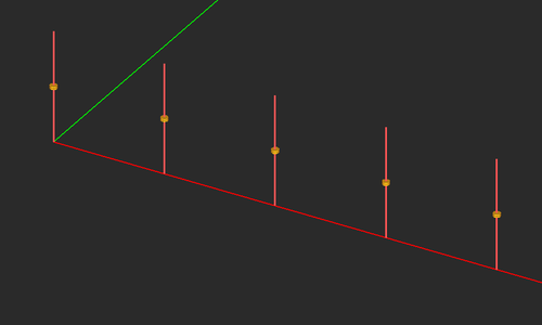
| + | NOTES, SPECIAL CASES OR EXCEPTIONS: In [[EM.Tempo]], the patch antenna is fed by a lumped source on a short vertical PEC line. In [[EM.Picasso]], the patch antenna is fed by a probe source on a short vertical PEC via. In both modules, the dimensions of the square patch are set equal to 0.47 times the effective dielectric wavelength, which can be changed. In [[EM.Tempo]], the total dimensions of the substrate are set equal to 1.2 times the overall dimensions of all the units cells, which can be changed, too. | ||
| + | |||
| + | |||
| + | PYTHON COMMAND(S): | ||
| + | |||
| + | emag_patch_array_tempo(h,er,feed_ratio,nx,ny,spacing_lambda) | ||
| + | |||
| + | emag_patch_array_picasso(h,er,feed_ratio,feed_rad,nx,ny,spacing_lambda) | ||
| + | |||
| + | |||
| + | PATCH ARRAY WIZARD PARAMETERS | ||
| + | {| border="0" | ||
| + | |- | ||
| + | | valign="top"| | ||
| + | |- | ||
| + | {| class="wikitable" | ||
| + | |- | ||
| + | ! scope="col"| Parameter Name | ||
| + | ! scope="col"| Value Type | ||
| + | ! scope="col"| Units | ||
| + | ! scope="col"| Default Value | ||
| + | ! scope="col"| Notes | ||
| + | |- | ||
| + | ! scope="row" | h | ||
| + | | real numeric | ||
| + | | meter | ||
| + | | 0.0015 | ||
| + | | substrate thickness (height) | ||
| + | |- | ||
| + | ! scope="row" | er | ||
| + | | real numeric | ||
| + | | - | ||
| + | | 2.2 | ||
| + | | substrate relative permittivity | ||
| + | |- | ||
| + | ! scope="row" | feed_ratio | ||
| + | | real numeric | ||
| + | | - | ||
| + | | 0.4 | ||
| + | | ratio of location of probe to half patch length xf/(a/2) | ||
| + | |- | ||
| + | ! scope="row" | feed_rad | ||
| + | | real numeric | ||
| + | | - | ||
| + | | 0.0025 | ||
| + | | radius of probe via (only in [[EM.Picasso]]) | ||
| + | |- | ||
| + | ! scope="row" | nx | ||
| + | | integer numeric | ||
| + | | - | ||
| + | | 2 | ||
| + | | number of elements along X | ||
| + | |- | ||
| + | ! scope="row" | ny | ||
| + | | integer numeric | ||
| + | | - | ||
| + | | 2 | ||
| + | | number of elements along Y | ||
| + | |- | ||
| + | ! scope="row" | spacing_lambda | ||
| + | | real numeric | ||
| + | | - | ||
| + | | 0.5 | ||
| + | | element spacing normalized to free-space wavelength | ||
| + | |} | ||
| + | |||
| + | <table> | ||
| + | <tr> | ||
| + | <td> | ||
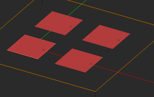
| + | [[Image:wiz_patch_array_tempo.png|thumb|500px|Default probe-fed patch antenna array in EM.Tempo.]] | ||
| + | </td> | ||
| + | </tr> | ||
| + | <tr> | ||
| + | <td> | ||
| + | [[Image:wiz_patch_array_picasso.png|thumb|500px|Default probe-fed patch antenna array in EM.Picasso.]] | ||
| + | </td> | ||
| + | </tr> | ||
| + | </table> | ||
| + | |||
| + | == Probe-Fed Patch Wizard == | ||
| + | |||
| + | ICON: [[File:probe_patch_icon.png]] | ||
| + | |||
| + | MENU: '''Tools → Antenna Wizards → Probe-Fed Patch Antenna''' | ||
| + | |||
| + | MODULE(S): [[EM.Tempo]], [[EM.Picasso]] | ||
| + | |||
| + | FUNCTION: Creates the parameterized geometry of a probe-fed rectangular patch antenna in the project workspace | ||
| + | |||
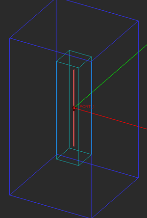
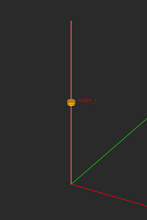
| + | NOTES, SPECIAL CASES OR EXCEPTIONS: In [[EM.Tempo]], the patch antenna is fed by a lumped source on a short vertical PEC line. In [[EM.Picasso]], the patch antenna is fed by a probe source on a short vertical PEC via. In both modules, the dimensions of the square patch are set equal to 0.47 times the effective dielectric wavelength, which can be changed. | ||
| + | |||
| + | |||
| + | PYTHON COMMAND(S): | ||
| + | |||
| + | emag_patch_tempo(h,er,feed_ratio,sub_size) | ||
| + | |||
| + | emag_patch_picasso(h,er,feed_ratio,feed_rad) | ||
| + | |||
| + | |||
| + | PATCH WIZARD PARAMETERS | ||
| + | {| border="0" | ||
| + | |- | ||
| + | | valign="top"| | ||
| + | |- | ||
| + | {| class="wikitable" | ||
| + | |- | ||
| + | ! scope="col"| Parameter Name | ||
| + | ! scope="col"| Value Type | ||
| + | ! scope="col"| Units | ||
| + | ! scope="col"| Default Value | ||
| + | ! scope="col"| Notes | ||
| + | |- | ||
| + | ! scope="row" | h | ||
| + | | real numeric | ||
| + | | meter | ||
| + | | 0.0015 | ||
| + | | substrate thickness (height) | ||
| + | |- | ||
| + | ! scope="row" | er | ||
| + | | real numeric | ||
| + | | - | ||
| + | | 2.2 | ||
| + | | substrate relative permittivity | ||
| + | |- | ||
| + | ! scope="row" | feed_ratio | ||
| + | | real numeric | ||
| + | | - | ||
| + | | 0.4 | ||
| + | | ratio of location of probe to half patch length xf/(a/2) | ||
| + | |- | ||
| + | ! scope="row" | feed_rad | ||
| + | | real numeric | ||
| + | | meter | ||
| + | | 0.005 | ||
| + | | radius of probe via | ||
| + | |- | ||
| + | ! scope="row" | sub_size | ||
| + | | real numeric | ||
| + | | meter | ||
| + | | 0.15 | ||
| + | | substrate dimensions along X and Y (only in [[EM.Tempo]]) | ||
| + | |} | ||
| + | |||
| + | <table> | ||
| + | <tr> | ||
| + | <td> | ||
| + | [[Image:wiz_patch_tempo.png|thumb|500px|Default probe-fed patch antenna in EM.Tempo.]] | ||
| + | </td> | ||
| + | </tr> | ||
| + | <tr> | ||
| + | <td> | ||
| + | [[Image:wiz_patch_picasso.png|thumb|500px|Default probe-fed patch antenna in EM.Picasso.]] | ||
</td> | </td> | ||
</tr> | </tr> | ||
| Line 1,683: | Line 2,115: | ||
<td> | <td> | ||
[[Image:wiz_wg_tempo.png|thumb|500px|Default rectangular waveguide segment with a shorted end wall in EM.Tempo.]] | [[Image:wiz_wg_tempo.png|thumb|500px|Default rectangular waveguide segment with a shorted end wall in EM.Tempo.]] | ||
| + | </td> | ||
| + | </tr> | ||
| + | </table> | ||
| + | |||
| + | == Sierpinski Wizard == | ||
| + | |||
| + | ICON: [[File:sierpin icon.png]] | ||
| + | |||
| + | MENU: '''Tools → Component Wizards → Sierpinski Strip''' | ||
| + | |||
| + | MODULE(S): [[Building_Geometrical_Constructions_in_CubeCAD | CubeCAD]], [[EM.Tempo]], [[EM.Illumina]], [[EM.Ferma]], [[EM.Picasso]], [[EM.Libera]] | ||
| + | |||
| + | FUNCTION: Creates the geometry of a Sierpinski triangle fractal in the project workspace | ||
| + | |||
| + | NOTES, SPECIAL CASES OR EXCEPTIONS: A dialog asks you to enter values for the key size and number of fractal levels. The wizard creates the Sierpinski triangle as a large set of smaller triangles, which cannot be modified using variables afterwards. You may want to group the set of all the triangles as a single composite object. | ||
| + | |||
| + | |||
| + | PYTHON COMMAND(S): emag_sierpinski(key_size,levels) | ||
| + | |||
| + | |||
| + | SIERPINSKI WIZARD PARAMETERS | ||
| + | {| border="0" | ||
| + | |- | ||
| + | | valign="top"| | ||
| + | |- | ||
| + | {| class="wikitable" | ||
| + | |- | ||
| + | ! scope="col"| Parameter Name | ||
| + | ! scope="col"| Value Type | ||
| + | ! scope="col"| Units | ||
| + | ! scope="col"| Default Value | ||
| + | ! scope="col"| Notes | ||
| + | |- | ||
| + | ! scope="row" | key_size | ||
| + | | real numeric | ||
| + | | project units | ||
| + | | 100 | ||
| + | | side length of the largest (outermost) triangle | ||
| + | |- | ||
| + | ! scope="row" | levels | ||
| + | | integer numeric | ||
| + | | - | ||
| + | | 3 | ||
| + | | number of fractal levels | ||
| + | |} | ||
| + | |||
| + | <table> | ||
| + | <tr> | ||
| + | <td> | ||
| + | [[Image:wiz_sierpin_tempo.png|thumb|500px|Default Sierpinski triangle strip in EM.Tempo.]] | ||
</td> | </td> | ||
</tr> | </tr> | ||
| Line 1,860: | Line 2,342: | ||
<td> | <td> | ||
[[Image:wiz_slot_picasso.png|thumb|500px|Default slot antenna in EM.Picasso.]] | [[Image:wiz_slot_picasso.png|thumb|500px|Default slot antenna in EM.Picasso.]] | ||
| + | </td> | ||
| + | </tr> | ||
| + | </table> | ||
| + | |||
| + | == Slot-Coupled Patch Wizard == | ||
| + | |||
| + | ICON: [[File:slot_patch_icon.png]] | ||
| + | |||
| + | MENU: '''Tools → Antenna Wizards → Slot-Coupled Patch Antenna''' | ||
| + | |||
| + | MODULE(S): [[EM.Tempo]], [[EM.Picasso]] | ||
| + | |||
| + | FUNCTION: Creates the parameterized geometry of a slot-coupled rectangular patch antenna in the project workspace | ||
| + | |||
| + | NOTES, SPECIAL CASES OR EXCEPTIONS: This wizard creates a substrate with two dielectric layers, which are separated by a PEC ground plane hosting a coupling slot. The upper layer hosts a rectangular patch antenna. The bottom layer hosts a microstrip feed line with an open stub, which is extended past the slot location. The total dimensions of the square patch are set equal to 0.47 times the effective dielectric wavelength, which can be changed. The length of the open stub beyond the slot location is set equal to a quarter guide wavelength, which can be changed, too. | ||
| + | |||
| + | |||
| + | PYTHON COMMAND(S): | ||
| + | |||
| + | emag_slot_coupled_patch_tempo(h_patch,er_patch,h_feed,er_feed,slot_len,slot_wid,z0,feed_len,sub_len,sub_wid) | ||
| + | |||
| + | emag_slot_coupled_patch_picasso(h_patch,er_patch,h_feed,er_feed,slot_len,slot_wid,z0,feed_len) | ||
| + | |||
| + | |||
| + | SLOT-COUPLED PATCH WIZARD PARAMETERS | ||
| + | {| border="0" | ||
| + | |- | ||
| + | | valign="top"| | ||
| + | |- | ||
| + | {| class="wikitable" | ||
| + | |- | ||
| + | ! scope="col"| Parameter Name | ||
| + | ! scope="col"| Value Type | ||
| + | ! scope="col"| Units | ||
| + | ! scope="col"| Default Value | ||
| + | ! scope="col"| Notes | ||
| + | |- | ||
| + | ! scope="row" | h_patch | ||
| + | | real numeric | ||
| + | | meter | ||
| + | | 0.0015 | ||
| + | | thickness (height) of the top substrate layer | ||
| + | |- | ||
| + | ! scope="row" | er_patch | ||
| + | | real numeric | ||
| + | | - | ||
| + | | 2.2 | ||
| + | | relative permittivity of the top substrate layer | ||
| + | |- | ||
| + | ! scope="row" | h_feed | ||
| + | | real numeric | ||
| + | | meter | ||
| + | | 0.0015 | ||
| + | | thickness (height) of the bottom substrate layer | ||
| + | |- | ||
| + | ! scope="row" | er_feed | ||
| + | | real numeric | ||
| + | | - | ||
| + | | 2.2 | ||
| + | | relative permittivity of the bottom substrate layer | ||
| + | |- | ||
| + | ! scope="row" | slot_len | ||
| + | | real numeric | ||
| + | | meter | ||
| + | | 0.02 | ||
| + | | length of the coupling slot | ||
| + | |- | ||
| + | ! scope="row" | slot_wid | ||
| + | | real numeric | ||
| + | | meter | ||
| + | | 0.0025 | ||
| + | | width of the coupling slot | ||
| + | |- | ||
| + | ! scope="row" | z0 | ||
| + | | real numeric | ||
| + | | Ohms | ||
| + | | 50 | ||
| + | | characteristic impedance of the microstrip feed | ||
| + | |- | ||
| + | ! scope="row" | feed_len | ||
| + | | real numeric | ||
| + | | meter | ||
| + | | 0.1 | ||
| + | | length of the microstrip feed line | ||
| + | |- | ||
| + | ! scope="row" | sub_len | ||
| + | | real numeric | ||
| + | | meter | ||
| + | | 0.3 | ||
| + | | substrate dimension along X (only in [[EM.Tempo]]) | ||
| + | |- | ||
| + | ! scope="row" | sub_wid | ||
| + | | real numeric | ||
| + | | meter | ||
| + | | 0.3 | ||
| + | | substrate dimension along Y (only in [[EM.Tempo]]) | ||
| + | |} | ||
| + | |||
| + | <table> | ||
| + | <tr> | ||
| + | <td> | ||
| + | [[Image:wiz_slot_patch_tempo.png|thumb|500px|Default slot-coupled patch antenna in EM.Tempo with the patch, middle ground and substrate layers in the freeze state.]] | ||
| + | </td> | ||
| + | </tr> | ||
| + | <tr> | ||
| + | <td> | ||
| + | [[Image:wiz_slot_patch_picasso.png|thumb|500px|Default slot-coupled patch antenna in EM.Picasso with the patch in the freeze state.]] | ||
</td> | </td> | ||
</tr> | </tr> | ||
| Line 1,959: | Line 2,548: | ||
</table> | </table> | ||
| − | == | + | == Trihedral Reflector Wizard == |
| − | ICON: [[File: | + | ICON: [[File:trihed icon.png]] |
| − | MENU: '''Tools → | + | MENU: '''Tools → Component Wizards → Trihedral Reflector''' |
| − | MODULE(S): [[EM.Tempo]], [[EM. | + | MODULE(S): [[Building_Geometrical_Constructions_in_CubeCAD | CubeCAD]], [[EM.Tempo]], [[EM.Illumina]], [[EM.Ferma]], [[EM.Libera]] |
| − | FUNCTION: Creates the parameterized geometry of a | + | FUNCTION: Creates the parameterized geometry of a Trihedral corner reflector in the project workspace |
| − | NOTES, SPECIAL CASES OR EXCEPTIONS: | + | NOTES, SPECIAL CASES OR EXCEPTIONS: The aperture diameter of the reflector is determined based on the focal and axial lengths of the primitive parabola. |
| − | PYTHON COMMAND(S): | + | PYTHON COMMAND(S): emag_trihedral_reflector(side) |
| − | |||
| − | + | TRIHEDRAL REFLECTOR WIZARD PARAMETERS | |
| − | + | ||
| − | + | ||
| − | + | ||
{| border="0" | {| border="0" | ||
|- | |- | ||
| Line 1,992: | Line 2,577: | ||
! scope="col"| Notes | ! scope="col"| Notes | ||
|- | |- | ||
| − | ! scope="row" | | + | ! scope="row" | side |
| real numeric | | real numeric | ||
| − | | | + | | project units |
| − | | | + | | 100 |
| − | | | + | | square wall dimensions |
| + | |} | ||
| + | |||
| + | <table> | ||
| + | <tr> | ||
| + | <td> | ||
| + | [[Image:wiz_trihed_tempo.png|thumb|360px|Default trihedral reflector in EM.Tempo.]] | ||
| + | </td> | ||
| + | </tr> | ||
| + | </table> | ||
| + | |||
| + | == Two-Port Coaxial Wizard == | ||
| + | |||
| + | ICON: [[File:coax2p icon.png]] | ||
| + | |||
| + | MENU: '''Tools → Transmission Line Wizards → Two-Port Coaxial Line''' | ||
| + | |||
| + | MODULE(S): [[EM.Tempo]] | ||
| + | |||
| + | FUNCTION: Creates the parameterized geometry of a two-port coaxial line segment of a specified characteristic impedance with a dielectric core in the project workspace | ||
| + | |||
| + | NOTES, SPECIAL CASES OR EXCEPTIONS: The radius of the outer conductor is determined based on the specified characteristic impedance. It may be replaced by a numeric value instead. | ||
| + | |||
| + | |||
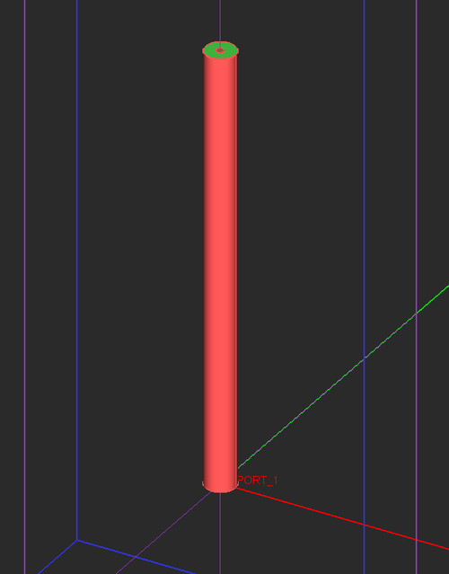
| + | PYTHON COMMAND(S): emag_coax_2port_tempo(er,z0,r_inner,len) | ||
| + | |||
| + | |||
| + | TWO-PORT COAXIAL WIZARD PARAMETERS | ||
| + | {| border="0" | ||
| + | |- | ||
| + | | valign="top"| | ||
| + | |- | ||
| + | {| class="wikitable" | ||
| + | |- | ||
| + | ! scope="col"| Parameter Name | ||
| + | ! scope="col"| Value Type | ||
| + | ! scope="col"| Units | ||
| + | ! scope="col"| Default Value | ||
| + | ! scope="col"| Notes | ||
|- | |- | ||
! scope="row" | er | ! scope="row" | er | ||
| Line 2,002: | Line 2,625: | ||
| - | | - | ||
| 2.2 | | 2.2 | ||
| − | | | + | | relative permittivity of the dielectric core |
|- | |- | ||
! scope="row" | z0 | ! scope="row" | z0 | ||
| Line 2,010: | Line 2,633: | ||
| characteristic impedance | | characteristic impedance | ||
|- | |- | ||
| − | ! scope="row" | | + | ! scope="row" | r_inner |
| real numeric | | real numeric | ||
| meters | | meters | ||
| − | | | + | | 0.001 |
| − | | | + | | radius of inner conductor |
|- | |- | ||
| − | ! scope="row" | | + | ! scope="row" | len |
| real numeric | | real numeric | ||
| meters | | meters | ||
| - | | - | ||
| − | | length of | + | | length of the line segment (only in [[EM.Tempo]]) |
| − | + | ||
| − | + | ||
| − | + | ||
| − | + | ||
| − | + | ||
| − | + | ||
| − | + | ||
| − | + | ||
| − | + | ||
| − | + | ||
| − | + | ||
| − | + | ||
| − | + | ||
| − | + | ||
| − | + | ||
| − | + | ||
| − | + | ||
| − | + | ||
|} | |} | ||
| Line 2,044: | Line 2,649: | ||
<tr> | <tr> | ||
<td> | <td> | ||
| − | [[Image: | + | [[Image:wiz_coax2p_tempo.png|thumb|500px|Default two-port coaxial line segment in EM.Tempo.]] |
| − | + | ||
| − | + | ||
| − | + | ||
| − | + | ||
| − | + | ||
</td> | </td> | ||
</tr> | </tr> | ||
| Line 2,149: | Line 2,749: | ||
</table> | </table> | ||
| − | == Two-Port | + | == Two-Port Microstrip Wizard == |
| − | ICON: [[File: | + | ICON: [[File:us2p icon.png]] |
| − | MENU: '''Tools → Transmission Line Wizards → Two-Port | + | MENU: '''Tools → Transmission Line Wizards → Two-Port Microstrip Line''' |
| − | MODULE(S): [[EM.Tempo]] | + | MODULE(S): [[EM.Tempo]], [[EM.Picasso]] |
| − | FUNCTION: Creates the parameterized geometry of a two-port | + | FUNCTION: Creates the parameterized geometry of a two-port microstrip line segment of a specified characteristic impedance on a conductor-backed single-layer dielectric substrate in the project workspace |
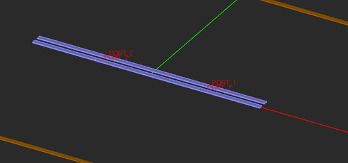
| − | NOTES, SPECIAL CASES OR EXCEPTIONS: The | + | NOTES, SPECIAL CASES OR EXCEPTIONS: In [[EM.Tempo]], the two ports are placed at the two edges of the substrate. The width of the microstrip lines is determined based on the specified characteristic impedance. It may be replaced by a numeric value instead. |
| − | PYTHON COMMAND(S): | + | PYTHON COMMAND(S): |
| + | emag_microstrip_2port_tempo(h,er,z0,strip_len,sub_len,sub_wid,draw_substrate) | ||
| − | TWO-PORT | + | emag_microstrip_2port_picasso(h,er,z0,strip_len,feed_len) |
| + | |||
| + | |||
| + | TWO-PORT MICROSTRIP WIZARD PARAMETERS | ||
{| border="0" | {| border="0" | ||
|- | |- | ||
| Line 2,177: | Line 2,781: | ||
! scope="col"| Default Value | ! scope="col"| Default Value | ||
! scope="col"| Notes | ! scope="col"| Notes | ||
| + | |- | ||
| + | ! scope="row" | h | ||
| + | | real numeric | ||
| + | | meters | ||
| + | | 0.0015 | ||
| + | | substrate height (thickness) | ||
|- | |- | ||
! scope="row" | er | ! scope="row" | er | ||
| Line 2,182: | Line 2,792: | ||
| - | | - | ||
| 2.2 | | 2.2 | ||
| − | | relative permittivity | + | | substrate relative permittivity |
|- | |- | ||
! scope="row" | z0 | ! scope="row" | z0 | ||
| Line 2,190: | Line 2,800: | ||
| characteristic impedance | | characteristic impedance | ||
|- | |- | ||
| − | ! scope="row" | | + | ! scope="row" | strip_len |
| real numeric | | real numeric | ||
| meters | | meters | ||
| − | | | + | | - |
| − | | | + | | length of the line segment |
|- | |- | ||
| − | ! scope="row" | | + | ! scope="row" | feed_len |
| real numeric | | real numeric | ||
| meters | | meters | ||
| - | | - | ||
| − | | length of | + | | length of feed line (only in [[EM.Picasso]]) |
| + | |- | ||
| + | ! scope="row" | sub_len | ||
| + | | real numeric | ||
| + | | meters | ||
| + | | - | ||
| + | | length of substrate (only in [[EM.Tempo]]) | ||
| + | |- | ||
| + | ! scope="row" | sub_wid | ||
| + | | real numeric | ||
| + | | meters | ||
| + | | - | ||
| + | | width of substrate (only in [[EM.Tempo]]) | ||
| + | |- | ||
| + | ! scope="row" | draw_substrate | ||
| + | | Boolean | ||
| + | | - | ||
| + | | True | ||
| + | | Adds substrate & ground plane | ||
|} | |} | ||
| Line 2,206: | Line 2,834: | ||
<tr> | <tr> | ||
<td> | <td> | ||
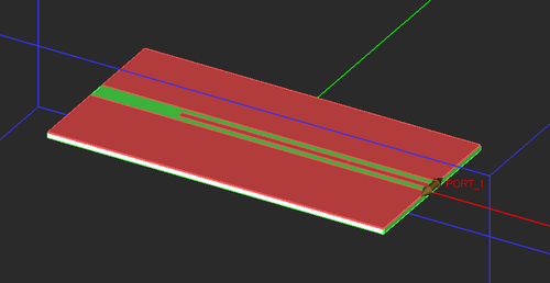
| − | [[Image: | + | [[Image:wiz_us2p_tempo.png|thumb|500px|Default two-port microstrip line segment in EM.Tempo.]] |
| + | </td> | ||
| + | </tr> | ||
| + | <tr> | ||
| + | <td> | ||
| + | [[Image:wiz_us2p_picasso.png|thumb|500px|Default two-port microstrip line segment in EM.Picasso.]] | ||
</td> | </td> | ||
</tr> | </tr> | ||
| Line 2,263: | Line 2,896: | ||
<td> | <td> | ||
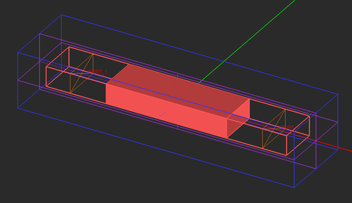
[[Image:wiz_wg2p_tempo.png|thumb|500px|Default two-port rectangular waveguide segment in EM.Tempo with the two open-end feed sections in the freeze state.]] | [[Image:wiz_wg2p_tempo.png|thumb|500px|Default two-port rectangular waveguide segment in EM.Tempo with the two open-end feed sections in the freeze state.]] | ||
| − | |||
| − | |||
| − | |||
| − | |||
| − | |||
| − | |||
| − | |||
| − | |||
| − | |||
| − | |||
| − | |||
| − | |||
| − | |||
| − | |||
| − | |||
| − | |||
| − | |||
| − | |||
| − | |||
| − | |||
| − | |||
| − | |||
| − | |||
| − | |||
| − | |||
| − | |||
| − | |||
| − | |||
| − | |||
| − | |||
| − | |||
| − | |||
| − | |||
| − | |||
| − | |||
| − | |||
| − | |||
| − | |||
| − | |||
| − | |||
| − | |||
| − | |||
| − | |||
| − | |||
| − | |||
| − | |||
| − | |||
| − | |||
| − | |||
| − | |||
| − | |||
| − | |||
| − | |||
| − | |||
| − | |||
| − | |||
| − | |||
| − | |||
| − | |||
| − | |||
| − | |||
| − | |||
| − | |||
| − | |||
| − | |||
| − | |||
| − | |||
| − | |||
| − | |||
| − | |||
| − | |||
| − | |||
| − | |||
| − | |||
| − | |||
| − | |||
| − | |||
| − | |||
| − | |||
| − | |||
| − | |||
| − | |||
| − | |||
| − | |||
| − | |||
| − | |||
| − | |||
| − | |||
| − | |||
| − | |||
| − | |||
| − | |||
| − | |||
| − | |||
| − | |||
| − | |||
| − | |||
| − | |||
| − | |||
| − | |||
| − | |||
| − | |||
| − | |||
| − | |||
| − | |||
| − | |||
| − | |||
| − | |||
| − | |||
| − | |||
| − | |||
| − | |||
| − | |||
| − | |||
| − | |||
| − | |||
| − | |||
| − | |||
| − | |||
| − | |||
| − | |||
| − | |||
| − | |||
| − | |||
| − | |||
| − | |||
| − | |||
| − | |||
| − | |||
| − | |||
| − | |||
| − | |||
| − | |||
| − | |||
| − | |||
| − | |||
| − | |||
| − | |||
| − | |||
| − | |||
| − | |||
| − | |||
| − | |||
| − | |||
| − | |||
| − | |||
| − | |||
| − | |||
| − | |||
| − | |||
| − | |||
| − | |||
| − | |||
| − | |||
| − | |||
| − | |||
| − | |||
| − | |||
| − | |||
| − | |||
| − | |||
| − | |||
| − | |||
| − | |||
| − | |||
| − | |||
| − | |||
| − | |||
| − | |||
| − | |||
| − | |||
| − | |||
| − | |||
| − | |||
| − | |||
| − | |||
| − | |||
| − | |||
| − | |||
| − | |||
| − | |||
| − | |||
| − | |||
| − | |||
| − | |||
| − | |||
| − | |||
| − | |||
| − | |||
| − | |||
| − | |||
| − | |||
| − | |||
| − | |||
| − | |||
| − | |||
| − | |||
| − | |||
| − | |||
| − | |||
| − | |||
| − | |||
| − | |||
| − | |||
| − | |||
| − | |||
| − | |||
| − | |||
| − | |||
| − | |||
| − | |||
| − | |||
| − | |||
| − | |||
| − | |||
| − | |||
| − | |||
| − | |||
| − | |||
| − | |||
| − | |||
| − | |||
| − | |||
| − | |||
| − | |||
| − | |||
| − | |||
| − | |||
| − | |||
| − | |||
| − | |||
| − | |||
| − | |||
| − | |||
| − | |||
| − | |||
| − | |||
| − | |||
| − | |||
| − | |||
| − | |||
| − | |||
| − | |||
| − | |||
| − | |||
| − | |||
| − | |||
| − | |||
| − | |||
| − | |||
| − | |||
| − | |||
| − | |||
| − | |||
| − | |||
| − | |||
| − | |||
| − | |||
| − | |||
| − | |||
| − | |||
| − | |||
| − | |||
| − | |||
| − | |||
| − | |||
| − | |||
| − | |||
| − | |||
| − | |||
| − | |||
| − | |||
| − | |||
| − | |||
| − | |||
| − | |||
| − | |||
| − | |||
| − | |||
| − | |||
| − | |||
| − | |||
| − | |||
| − | |||
| − | |||
| − | |||
| − | |||
| − | |||
| − | |||
| − | |||
| − | |||
| − | |||
| − | |||
| − | |||
| − | |||
| − | |||
| − | |||
| − | |||
| − | |||
| − | |||
| − | |||
| − | |||
| − | |||
| − | |||
| − | |||
| − | |||
| − | |||
| − | |||
| − | |||
| − | |||
| − | |||
| − | |||
| − | |||
| − | |||
| − | |||
| − | |||
| − | |||
| − | |||
| − | |||
| − | |||
| − | |||
| − | |||
| − | |||
| − | |||
| − | |||
| − | |||
| − | |||
| − | |||
| − | |||
| − | |||
| − | |||
| − | |||
| − | |||
| − | |||
| − | |||
| − | |||
| − | |||
| − | |||
| − | |||
| − | |||
| − | |||
| − | |||
| − | |||
| − | |||
| − | |||
| − | |||
| − | |||
| − | |||
| − | |||
| − | |||
| − | |||
| − | |||
| − | |||
| − | |||
| − | |||
| − | |||
| − | |||
| − | |||
| − | |||
| − | |||
| − | |||
| − | |||
| − | |||
| − | |||
| − | |||
| − | |||
| − | |||
| − | |||
| − | |||
| − | |||
| − | |||
| − | |||
| − | |||
| − | |||
| − | |||
| − | |||
| − | |||
| − | |||
| − | |||
| − | |||
| − | |||
| − | |||
| − | |||
| − | |||
| − | |||
| − | |||
| − | |||
| − | |||
| − | |||
| − | |||
| − | |||
| − | |||
| − | |||
| − | |||
| − | |||
| − | |||
| − | |||
| − | |||
| − | |||
| − | |||
| − | |||
| − | |||
| − | |||
| − | |||
| − | |||
| − | |||
| − | |||
| − | |||
| − | |||
| − | |||
| − | |||
| − | |||
| − | |||
| − | |||
| − | |||
| − | |||
| − | |||
| − | |||
| − | |||
| − | |||
| − | |||
| − | |||
| − | |||
| − | |||
| − | |||
| − | |||
| − | |||
| − | |||
| − | |||
| − | |||
| − | |||
| − | |||
| − | |||
| − | |||
| − | |||
| − | |||
| − | |||
| − | |||
| − | |||
| − | |||
| − | |||
| − | |||
| − | |||
| − | |||
| − | |||
| − | |||
| − | |||
| − | |||
| − | |||
| − | |||
| − | |||
| − | |||
| − | |||
| − | |||
| − | |||
| − | |||
| − | |||
| − | |||
| − | |||
| − | |||
| − | |||
| − | |||
| − | |||
| − | |||
| − | |||
| − | |||
| − | |||
| − | |||
| − | |||
| − | |||
| − | |||
| − | |||
| − | |||
| − | |||
| − | |||
| − | |||
| − | |||
| − | |||
| − | |||
| − | |||
| − | |||
| − | |||
| − | |||
| − | |||
| − | |||
| − | |||
| − | |||
| − | |||
| − | |||
| − | |||
| − | |||
| − | |||
| − | |||
| − | |||
| − | |||
| − | |||
| − | |||
| − | |||
| − | |||
| − | |||
| − | |||
| − | |||
| − | |||
| − | |||
| − | |||
| − | |||
| − | |||
| − | |||
| − | |||
| − | |||
| − | |||
| − | |||
| − | |||
| − | |||
| − | |||
| − | |||
| − | |||
| − | |||
| − | |||
| − | |||
| − | |||
| − | |||
| − | |||
| − | |||
| − | |||
| − | |||
| − | |||
| − | |||
| − | |||
| − | |||
| − | |||
| − | |||
| − | |||
| − | |||
| − | |||
| − | |||
| − | |||
| − | |||
| − | |||
| − | |||
| − | |||
| − | |||
| − | |||
| − | |||
| − | |||
| − | |||
| − | |||
| − | |||
| − | |||
| − | |||
| − | |||
| − | |||
| − | |||
| − | |||
| − | |||
| − | |||
| − | |||
| − | |||
| − | |||
| − | |||
| − | |||
| − | |||
| − | |||
| − | |||
| − | |||
| − | |||
| − | |||
| − | |||
| − | |||
| − | |||
| − | |||
| − | |||
| − | |||
| − | |||
| − | |||
| − | |||
| − | |||
| − | |||
| − | |||
| − | |||
| − | |||
| − | |||
| − | |||
| − | |||
| − | |||
| − | |||
| − | |||
| − | |||
| − | |||
| − | |||
| − | |||
| − | |||
| − | |||
| − | |||
| − | |||
| − | |||
| − | |||
| − | |||
| − | |||
| − | |||
| − | |||
| − | |||
| − | |||
| − | |||
| − | |||
| − | |||
| − | |||
| − | |||
| − | |||
| − | |||
| − | |||
| − | |||
| − | |||
| − | |||
| − | |||
| − | |||
| − | |||
| − | |||
| − | |||
| − | |||
| − | |||
| − | |||
| − | |||
| − | |||
| − | |||
| − | |||
| − | |||
| − | |||
| − | |||
| − | |||
| − | |||
| − | |||
| − | |||
</td> | </td> | ||
</tr> | </tr> | ||
Revision as of 23:24, 26 March 2017
Contents
- 1 Air Bridge Wizard
- 2 Coaxial Connector Wizard
- 3 Coaxial Wizard
- 4 Coil Wizard
- 5 Coplanar Waveguide (CPW) Wizard
- 6 Cross Slot Antenna Wizard
- 7 Cross Slot Wizard
- 8 Dipole Antenna Wizard
- 9 Dipole Array Wizard
- 10 Foil Wizard
- 11 Hilly Terrain Wizard
- 12 Horn Antenna Array Wizard
- 13 Horn Antenna Wizard
- 14 Linear Slot Array Wizard
- 15 Linear Slot Wizard
- 16 Microstrip Wizard
- 17 Microstrip-Fed Patch Wizard
- 18 Mountainous Terrain Wizard
- 19 Office Building Wizard
- 20 Parabolic Reflector Wizard
- 21 Particle Cloud Wizard
- 22 Plateau Terrain Wizard
- 23 Printed Dipole Wizard
- 24 Probe-Fed Patch Array Wizard
- 25 Probe-Fed Patch Wizard
- 26 Random City Wizard
- 27 Rectangular Waveguide Wizard
- 28 Sierpinski Wizard
- 29 Slot Antenna Array Wizard
- 30 Slot Antenna Wizard
- 31 Slot-Coupled Patch Wizard
- 32 Solenoid Wizard
- 33 Trihedral Reflector Wizard
- 34 Two-Port Coaxial Wizard
- 35 Two-Port Coplanar Waveguide (CPW) Wizard
- 36 Two-Port Microstrip Wizard
- 37 Two-Port Rectangular Waveguide Wizard
- 38 Yagi-Uda Array Wizard
Air Bridge Wizard
MENU: Tools → Component Wizards → Air Bridge
MODULE(S): EM.Tempo, EM.Picasso
FUNCTION: Creates the parameterized geometry of an air bridge in the project workspace typically used to equalize the grounds of a CPW line
NOTES, SPECIAL CASES OR EXCEPTIONS: In EM.Tempo, this wizard creates a free-standing air bridge only. In EM.Picasso, it also creates and sets the substrate parameters.
PYTHON COMMAND(S):
emag_air_bridge_tempo(bridge_len,post_height,post_rad)
emag_air_bridge_picasso(h,er,bridge_len,post_height,post_rad)
AIR BRIDGE WIZARD PARAMETERS
| Parameter Name | Value Type | Units | Default Value | Notes |
|---|---|---|---|---|
| h | real numeric | meters | 0.0015 | substrate height (thickness) (only in EM.Picasso) |
| er | real numeric | - | 2.2 | substrate relative permittivity (only in EM.Picasso) |
| bridge_len | real numeric | meters | 0.01 (EM.Tempo) or 0.015 (EM.Picasso) | length of the bridge |
| post_height | real numeric | meters | 0.004 (EM.Tempo) or 0.002 (EM.Picasso) | height of the two posts |
| post_rad | real numeric | meters | 0.001 | radius of the two posts |
Coaxial Connector Wizard
MENU: Tools → Component Wizards → Coaxial Connector
MODULE(S): EM.Tempo
FUNCTION: Creates the parameterized geometry of a coaxial connector of a specified characteristic impedance in the project workspace
NOTES, SPECIAL CASES OR EXCEPTIONS: The radius of the outer conductor is determined based on the specified characteristic impedance. It may be replaced by a numeric value instead.
PYTHON COMMAND(S): emag_sma_connector(er,z0,inner_rad,flange_size,feed_len,ext_len)
COAXIAL CONNECTOR WIZARD PARAMETERS
| Parameter Name | Value Type | Units | Default Value | Notes |
|---|---|---|---|---|
| er | real numeric | - | 2.2 | relative permittivity of the dielectric core |
| z0 | real numeric | Ohms | 50 | characteristic impedance |
| inner_rad | real numeric | meters | 0.001 | radius of inner conductor |
| flange_size | real numeric | meters | 0.01 | lateral size of the flange |
| feed_len | real numeric | meters | 0.03 | length of the coaxial line segment |
| ext_len | real numeric | meters | 0.0025 | length of the inner conductor extension beyond the flange |
Coaxial Wizard
MENU: Tools → Transmission Line Wizards → Coaxial Line
FUNCTION: Creates the parameterized geometry of a coaxial line segment of a specified characteristic impedance with a dielectric core in the project workspace
NOTES, SPECIAL CASES OR EXCEPTIONS: In EM.Tempo, this wizard creates a one-port open-ended coaxial transmission line segment. In EM.Ferma, it sets up a 2D solution plane for quasi-static analysis of the coaxial transmission line. The radius of the outer conductor is determined based on the specified characteristic impedance. It may be replaced by a numeric value instead.
PYTHON COMMAND(S):
emag_coax_2port_tempo(er,z0,r_inner,len)
emag_coax_ferma(er,z0,r_inner)
COAXIAL WIZARD PARAMETERS
| Parameter Name | Value Type | Units | Default Value | Notes |
|---|---|---|---|---|
| er | real numeric | - | 2.2 | relative permittivity of the dielectric core |
| z0 | real numeric | Ohms | 50 | characteristic impedance |
| r_inner | real numeric | meters | 0.001 | radius of inner conductor |
| len | real numeric | meters | - | length of the line segment (only in EM.Tempo) |
Coil Wizard
MENU: Tools → Component Wizards → Toroidal Coil
MODULE(S): CubeCAD, EM.Tempo, EM.Ferma, EM.Libera
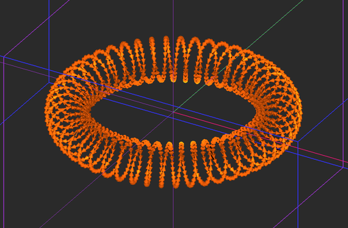
FUNCTION: Creates the parameterized geometry of a toroidal helix coil with a generalized super-quadratic cross section in the project workspace
NOTES, SPECIAL CASES OR EXCEPTIONS: In EM.Ferma, this wizard turns the toroidal coil into a wire current source.
PYTHON COMMAND(S):
emag_coil(major_rad,minor_rad_h,minor_rad_v,turns,order,step)
emag_coil_ferma(major_rad,minor_rad_h,minor_rad_v,turns,order,step,current,wire_rad)
COIL WIZARD PARAMETERS
| Parameter Name | Value Type | Units | Default Value | Notes |
|---|---|---|---|---|
| major_rad | real numeric | project units | 10 | radius of the circular axis |
| minor_rad_h | real numeric | project units | 2 | horizontal radius of the super-quadratic cross section |
| minor_rad_v | real numeric | project units | 2 | vertical radius of the super-quadratic cross section |
| turns | integer numeric | - | 50 | total number of turns |
| order | integer numeric | - | 2 | order of the super-quadratic curve, N = 2 produces an ellipse |
| step | real numeric | - | 0.005 | increment in the interval [0, 2*pi] - determines the resolution of the curve |
| current | real numeric | Amp | 1 | total current flowing through the coil (only in EM.Ferma) |
| wire_rad | real numeric | project units | 0.0005 | radius of the coil wire (only in EM.Ferma) |
Coplanar Waveguide (CPW) Wizard
MENU: Tools → Transmission Line Wizards → Coplanar Waveguide
MODULE(S): EM.Tempo, EM.Picasso, EM.Ferma
FUNCTION: Creates the parameterized geometry of a coplanar waveguide segment on a single-layer dielectric substrate in the project workspace
NOTES, SPECIAL CASES OR EXCEPTIONS: In EM.Tempo and EM.Picasso, this wizard creates a one-port open-ended CPW transmission line segment. In EM.Ferma, it sets up a 2D solution plane for quasi-static analysis of the CPW transmission line.
PYTHON COMMAND(S):
emag_cpw_tempo(h,er,strip_wid,slot_wid,strip_len,sub_len,sub_wid,draw_substrate)
emag_cpw_picasso(h,er,w,s,ls,lf)
emag_cpw_ferma(h,er,s,w,box_multiplier,draw_substrate)
CPW WIZARD PARAMETERS
| Parameter Name | Value Type | Units | Default Value | Notes |
|---|---|---|---|---|
| h | real numeric | meters | 0.0015 | substrate height (thickness) |
| er | real numeric | - | 2.2 | substrate relative permittivity |
| strip_wid | real numeric | meters | 0.002 | width of the center strip |
| slot_wid | real numeric | meters | 0.002 | width of the slots |
| strip_len | real numeric | meters | - | length of the line segment (only in EM.Tempo & EM.Picasso) |
| sub_len | real numeric | meters | - | length of substrate (only in EM.Tempo & EM.Ferma) |
| sub_wid | real numeric | meters | - | width of substrate (only in EM.Tempo & EM.Ferma) |
| draw_substrate | Boolean | - | True | Adds substrate & ground plane |
Cross Slot Antenna Wizard
MENU: Tools → Antenna Wizards → Cross Slot Antenna
MODULE(S): EM.Tempo, EM.Picasso
FUNCTION: Creates the parameterized geometry of a cross slot antenna in the project workspace
NOTES, SPECIAL CASES OR EXCEPTIONS: In EM.Tempo, the wizard creates a cross slot antenna on a dielectric substrate. In EM.Picasso, the wizard creates a cross slot antenna on a slot trace. The total length of each slot is set equal to a half the effective wavelength, which can be changed. This wizard does not provide a default excitation source in either module.
PYTHON COMMAND(S):
emag_slot_tempo(h,er,slot_wid,sub_size)
emag_slot_picasso(h,er,slot_wid)
CROSS SLOT ANTENNA WIZARD PARAMETERS
| Parameter Name | Value Type | Units | Default Value | Notes |
|---|---|---|---|---|
| h | real numeric | meter | 0.0015 | substrate thickness (height) |
| er | real numeric | - | 2.2 | substrate relative permittivity |
| slot_wid | real numeric | meter | 0.005 | width of the slot |
| sub_size | real numeric | meter | 0.2 | dimensions of the square substrate & ground (only in EM.Tempo) |
| </tr> |
Cross Slot Wizard
MENU: Tools → Antenna Wizards → Cross Slot
MODULE(S): CubeCAD, EM.Illumina, EM.Ferma, EM.Libera
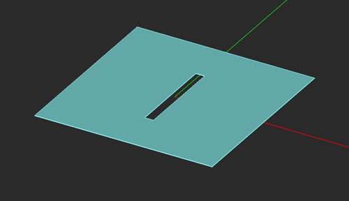
FUNCTION: Creates the parameterized geometry of a narrow cross slot in a ground plane
NOTES, SPECIAL CASES OR EXCEPTIONS: This wizard simply creates a cross slot in a ground plane using Boolean subtraction.
PYTHON COMMAND(S): emag_cross_slot(slot_len,slot_wid,metal_size)
LINEAR SLOT WIZARD PARAMETERS
| Parameter Name | Value Type | Units | Default Value | Notes |
|---|---|---|---|---|
| slot_len | real numeric | project units | 100 | total length of each slot arm |
| slot_wid | real numeric | project units | 10 | total width of each slot arm |
| metal_size | real numeric | project units | 200 | dimensions of the square metal ground |
Dipole Antenna Wizard
MENU: Tools → Antenna Wizards → Wire Dipole Antenna
MODULE(S): EM.Tempo, EM.Libera
FUNCTION: Creates the parameterized geometry of a dipole antenna in the project workspace
NOTES, SPECIAL CASES OR EXCEPTIONS: In EM.Tempo, the dipole consists of two thin PEC cylinders fed by a lumped source on a short joining line. In EM.Libera, the dipole is a thin wire.
PYTHON COMMAND(S):
emag_dipole_tempo(len_lambda,wire_rad_lambda)
emag_dipole_libera(len_lambda,wire_rad_lambda)
DIPOLE WIZARD PARAMETERS
| Parameter Name | Value Type | Units | Default Value | Notes |
|---|---|---|---|---|
| len_lambda | real numeric | - | 0.5 (in EM.Libera) or 0.47 (in EM.Tempo) | length of dipole normalized to free-space wavelength |
| wire_rad_lambda | real numeric | - | 0.002 | wire radius normalized to free-space wavelength |
Dipole Array Wizard
MENU: Tools → Antenna Wizards → Wire Dipole Array
MODULE(S): EM.Libera
FUNCTION: Creates the parameterized geometry of a dipole antenna array in the project workspace
NOTES, SPECIAL CASES OR EXCEPTIONS: The dipole elements are all thin wires.
PYTHON COMMAND(S): emag_dipole_array(len_lambda,spacing_lambda,nx,ny,wire_rad_lambda)
DIPOLE ARRAY WIZARD PARAMETERS
| Parameter Name | Value Type | Units | Default Value | Notes |
|---|---|---|---|---|
| len_lambda | real numeric | - | 0.5 | length of dipole normalized to free-space wavelength |
| spacing_lambda | real numeric | - | 0.5 | element spacing normalized to free-space wavelength |
| nx | integer numeric | - | 5 | number of elements along X |
| ny | integer numeric | - | 1 | number of elements along Y |
| wire_rad_lambda | real numeric | - | 0.002 | wire radius normalized to free-space wavelength |
Foil Wizard
MENU: Tools → Component Wizards → Conformal Coil
MODULE(S): CubeCAD, EM.Tempo, EM.Illumina, EM.Ferma, EM.Libera
FUNCTION: Creates the parameterized geometry of a cylindrical foil section in the project workspace
NOTES, SPECIAL CASES OR EXCEPTIONS: In EM.Tempo, this wizard creates a conformal metallic patch on a cylindrical dielectric coating around a cylindrical metal core. In all other modules, it creates a free-standing sectorial cylindrical foil.
PYTHON COMMAND(S):
emag_foil(foil_rad,foil_height,alpha)
emag_foil_tempo(er,core_rad,foil_rad,core_height,foil_height,foil_offset,alpha)
FOIL WIZARD PARAMETERS
| Parameter Name | Value Type | Units | Default Value | Notes |
|---|---|---|---|---|
| er | real numeric | - | 2.2 | relative permittivity of the dielectric coating (only in EM.Tempo) |
| core_rad | real numeric | project units | 20 | radius of the metal core (only in EM.Tempo) |
| foil_rad | real numeric | project units | 25 (in EM.Tempo) or 100 (all others) | radius of the foil section |
| core_height | real numeric | project units | 50 | height of the metal core (only in EM.Tempo) |
| foil_height | real numeric | project units | 25 (in EM.Tempo) or 100 (in all others) | height of the foil section |
| foil_offset | real numeric | project units | 10 | offset of the foil section with respect to the base of metal core (only in EM.Tempo) |
| alpha | real numeric | degrees | 90 | sectoral angle |
Hilly Terrain Wizard
MENU: Tools → Propagation Wizards → Hilly Terrain
MODULE(S): EM.Terrano
FUNCTION: Creates a hilly terrain with a random rough surface in the project workspace
NOTES, SPECIAL CASES OR EXCEPTIONS: This wizard creates a hilly terrain using a surface object generated with a Gaussian profile. The surface is then roughened based on the specified statistics.
PYTHON COMMAND(S): emag_hill(area_size,height,radius,elevation,res,rms_height,correl_len)
HILLY TERRAIN WIZARD PARAMETERS
| Parameter Name | Value Type | Units | Default Value | Notes |
|---|---|---|---|---|
| area_size | real numeric | meter | 50 | dimensions of the square terrain surface |
| height | real numeric | meter | 15 | height of the hill |
| radius | real numeric | meter | 20 | radius of the Gaussian surface profile |
| elevation | real numeric | meter | 1 | base elevation of whole terrain surface |
| res | real numeric | meter | 5 | resolution of terrain surface |
| rms_height | real numeric | meter | 1 | RMS height of the random rough surface |
| correl_len | real numeric | meter | 5 | correlation length of the random rough surface |
Horn Antenna Array Wizard
MENU: Tools → Antenna Wizards → Horn Antenna Array
MODULE(S): EM.Tempo
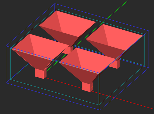
FUNCTION: Creates the parameterized geometry of a pyramidal horn antenna array in the project workspace
NOTES, SPECIAL CASES OR EXCEPTIONS: This wizard creates an array of pyramidal horn antennas fed by rectangular waveguides with a TE10 modal excitation. The larger dimension of each feeding waveguide is set slightly larger than half its cutoff wavelength for the dominant TE10 mode. The aspect ratio of each waveguide's cross section is 2:1. Its length is set to half the free-space wavelength. All of these dimensions can be replaced by arbitrary numeric values. The horn aperture dimensions and its overall length are calculated based on the specified antenna gain. All of these dimensions can be changed, too.
PYTHON COMMAND(S): emag_horn_array(gain_dB,nx,ny,spacing_x_lambda,spacing_y_lambda)
CROSS SLOT ANTENNA WIZARD PARAMETERS
| Parameter Name | Value Type | Units | Default Value | Notes |
|---|---|---|---|---|
| gain_dB | real numeric | - | 15 | gain of each individual horn element |
| nx | integer numeric | - | 2 | number of elements along X |
| ny | integer numeric | - | 2 | number of elements along Y |
| spacing_x_lambda | real numeric | - | 3 | element spacing along X normalized to free-space wavelength |
| spacing_y_lambda | real numeric | - | 3 | element spacing along Y normalized to free-space wavelength |
Horn Antenna Wizard
MENU: Tools → Antenna Wizards → Horn Antenna
MODULE(S): EM.Tempo
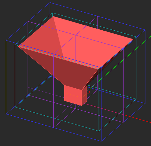
FUNCTION: Creates the parameterized geometry of a pyramidal horn antenna in the project workspace
NOTES, SPECIAL CASES OR EXCEPTIONS: This wizard creates a pyramidal horn antenna fed by a rectangular waveguide with a TE10 modal excitation. The larger dimension of the feeding waveguide is set slightly larger than half its cutoff wavelength for the dominant TE10 mode. The aspect ratio of the waveguide's cross section is 2:1. Its length is set to half the free-space wavelength. All of these dimensions can be replaced by arbitrary numeric values. The horn aperture dimensions and its overall length are calculated based on the specified antenna gain. All of these dimensions can be changed, too.
PYTHON COMMAND(S): emag_horn(gain_dB)
HORN ANTENNA WIZARD PARAMETERS
| Parameter Name | Value Type | Units | Default Value | Notes |
|---|---|---|---|---|
| gain_dB | real numeric | - | 15 | gain of the horn antenna |
Linear Slot Array Wizard
MENU: Tools → Antenna Wizards → Linear Slot Array
MODULE(S): CubeCAD, EM.Illumina, EM.Ferma, EM.Libera
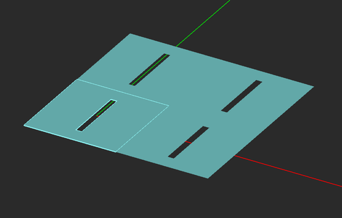
FUNCTION: Creates the parameterized geometry of an array of narrow rectangular slots in a ground plane
NOTES, SPECIAL CASES OR EXCEPTIONS: This wizard simply creates an array of linear slots in a ground plane using Boolean subtraction.
PYTHON COMMAND(S): emag_linear_slot_array(slot_len,slot_wid,nx,ny,spacing_x,spacing_y)
LINEAR SLOT ARRAY WIZARD PARAMETERS
| Parameter Name | Value Type | Units | Default Value | Notes |
|---|---|---|---|---|
| slot_len | real numeric | project units | 100 | length of the slot |
| slot_wid | real numeric | project units | 10 | width of the slot |
| nx | integer numeric | - | 2 | number of elements along X |
| ny | integer numeric | - | 2 | number of elements along Y |
| spacing_x | real numeric | - | 150 | element spacing along X |
| spacing_y | real numeric | - | 150 | element spacing along Y |
Linear Slot Wizard
MENU: Tools → Antenna Wizards → Linear Slot
MODULE(S): CubeCAD, EM.Illumina, EM.Ferma, EM.Libera
FUNCTION: Creates the parameterized geometry of a narrow rectangular slot in a ground plane
NOTES, SPECIAL CASES OR EXCEPTIONS: This wizard simply creates a linear slot in a ground plane using Boolean subtraction.
PYTHON COMMAND(S): emag_linear_slot(slot_len,slot_wid,metal_size)
LINEAR SLOT WIZARD PARAMETERS
| Parameter Name | Value Type | Units | Default Value | Notes |
|---|---|---|---|---|
| slot_len | real numeric | project units | 100 | length of the slot |
| slot_wid | real numeric | project units | 10 | width of the slot |
| metal_size | real numeric | project units | 200 | dimensions of the square metal ground |
Microstrip Wizard
MENU: Tools → Transmission Line Wizards → Microstrip Line
MODULE(S): EM.Tempo, EM.Picasso, EM.Ferma
FUNCTION: Creates the parameterized geometry of a microstrip line segment of a specified characteristic impedance on a conductor-backed single-layer dielectric substrate in the project workspace
NOTES, SPECIAL CASES OR EXCEPTIONS: In EM.Tempo and EM.Picasso, this wizard creates a one-port open-ended microstrip transmission line segment. In EM.Ferma, it sets up a 2D solution plane for quasi-static analysis of the microstrip transmission line. The width of the microstrip line is determined based on the specified characteristic impedance. It may be replaced by a numeric value instead.
PYTHON COMMAND(S):
emag_microstrip_tempo(h,er,z0,strip_len,feed_len,sub_len,sub_wid,draw_substrate)
emag_microstrip_picasso(h,er,z0,strip_len,feed_len)
emag_microstrip_ferma(h,er,z0,box_multiplier,draw_substrate)
MICROSTRIP WIZARD PARAMETERS
| Parameter Name | Value Type | Units | Default Value | Notes |
|---|---|---|---|---|
| h | real numeric | meters | 0.0015 | substrate height (thickness) |
| er | real numeric | - | 2.2 | substrate relative permittivity |
| z0 | real numeric | Ohms | 50 | characteristic impedance |
| strip_len | real numeric | meters | - | length of the line segment (only in EM.Tempo & EM.Picasso) |
| feed_len | real numeric | meters | - | length of feed line (only in EM.Tempo) |
| sub_len | real numeric | meters | - | length of substrate (only in EM.Tempo & EM.Ferma) |
| sub_wid | real numeric | meters | - | width of substrate (only in EM.Tempo & EM.Ferma) |
| draw_substrate | Boolean | - | True | Adds substrate & ground plane |
Microstrip-Fed Patch Wizard
MENU: Tools → Antenna Wizards → Microstrip-Fed Patch Antenna
MODULE(S): EM.Tempo, EM.Picasso
FUNCTION: Creates the parameterized geometry of a microstrip-fed rectangular patch antenna in the project workspace
NOTES, SPECIAL CASES OR EXCEPTIONS: The wizard asks you whether you want a microstrip-fed patch antenna with a recessed feed or one with a direct microstrip line junction. In EM.Tempo, the feed line is excited by a microstrip port. In EM.Picasso, the feed line has a scattering wave port. The total dimensions of the square patch are set equal to 0.5 times the effective dielectric wavelength, which can be changed.
PYTHON COMMAND(S):
emag_microstrip_fed_patch_tempo(is_recess,h,er,z0,feed_len,recess_dep,recess_wid,sub_len,sub_wid)
emag_microstrip_fed_patch_picasso(is_recess,h,er,z0,feed_len,recess_dep,recess_wid)
MICROSTRIP-FED PATCH WIZARD PARAMETERS
| Parameter Name | Value Type | Units | Default Value | Notes |
|---|---|---|---|---|
| is_recess | Boolean | - | True | Creates a recessed feed vs. a direct microstrip line junction to the patch |
| h | real numeric | meter | 0.0015 | substrate thickness (height) |
| er | real numeric | - | 2.2 | substrate relative permittivity |
| z0 | real numeric | Ohms | 50 | characteristic impedance of the microstrip feed |
| feed_len | real numeric | meter | 0.075 | length of the microstrip feed line |
| recess_dep | real numeric | meter | 0.015 | depth of the feed recess |
| recess_wid | real numeric | meter | 0.005 | width of the recess gaps |
| sub_len | real numeric | meter | 0.3 | substrate dimension along X (only in EM.Tempo) |
| sub_wid | real numeric | meter | 0.3 | substrate dimension along Y (only in EM.Tempo) |
Mountainous Terrain Wizard
MENU: Tools → Propagation Wizards → Mountainous Terrain
MODULE(S): EM.Terrano
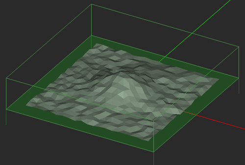
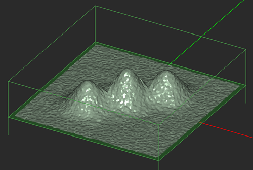
FUNCTION: Creates a mountainous terrain with a random rough surface in the project workspace
NOTES, SPECIAL CASES OR EXCEPTIONS: This wizard creates a mountainous terrain using a surface object generated with a bi-cubic spline profile. The surface is then roughened based on the specified statistics. This wizard can be used to create either a mountain range with three peaks or a single-peak mountain.
PYTHON COMMAND(S): emag_mountain(is_range,area_size,height,height_diff,radius,spacing,elevation,res,rms_height,correl_len)
MOUNTAINOUS TERRAIN WIZARD PARAMETERS
| Parameter Name | Value Type | Units | Default Value | Notes |
|---|---|---|---|---|
| is_range | Boolean | - | True | if true, creates a mountain range with three peaks, otherwise, creates a single peak |
| area_size | real numeric | meter | 200 | dimensions of the square terrain surface |
| height | real numeric | meter | 200 | height of the mountain |
| height_diff | real numeric | meter | 40 | difference between the heights of the center peak and the two lateral peaks in the case of a mountain range |
| radius | real numeric | meter | 50 | radius of the bi-cubic spline surface profile |
| spacing | real numeric | meter | 70 | spacing between the center peak and the two lateral peaks in the case of a mountain range |
| elevation | real numeric | meter | 1 | base elevation of whole terrain surface |
| res | real numeric | meter | 5 | resolution of terrain surface |
| rms_height | real numeric | meter | 1 | RMS height of the random rough surface |
| correl_len | real numeric | meter | 5 | correlation length of the random rough surface |
Office Building Wizard
MENU: Tools → Propagation Wizards → Office Building
MODULE(S): EM.Terrano
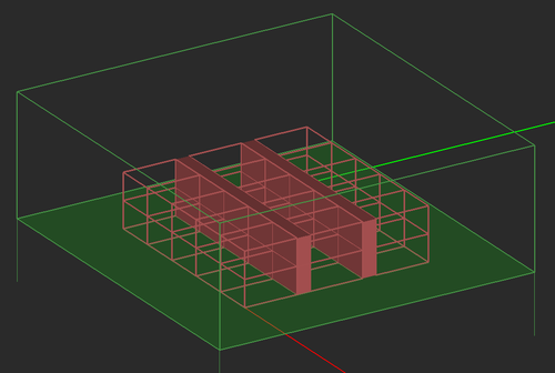
FUNCTION: Creates a multi-story office building with penetrable walls in the project workspace
NOTES, SPECIAL CASES OR EXCEPTIONS: This wizard creates an office building with multiple floor and rows of rooms separated by hallways.
PYTHON COMMAND(S): emag_office_building(room_len,room_wid,room_height,hallway_width,nx,ny,nz,er,sig,wall_thickness)
OFFICE BUILDING WIZARD PARAMETERS
| Parameter Name | Value Type | Units | Default Value | Notes |
|---|---|---|---|---|
| room_len | real numeric | meter | 6 | length of individual rooms |
| room_wid | real numeric | meter | 8 | width of individual rooms |
| room_height | real numeric | meter | 4 | height of individual rooms |
| hallway_wid | real numeric | meter | 2 | width of interior hallways |
| nx | integer numeric | - | 5 | number of rooms along X |
| ny | integer numeric | - | 3 | number of rooms along Y |
| nz | integer numeric | - | 2 | number of floors (number of rooms along Z) |
| er | real numeric | - | 4.4 | relative permittivity of building walls |
| sig | real numeric | S/m | 1e-3 | conductivity of building walls |
| wall_thickness | real numeric | meter | 0.25 | thickness of the individual walls |
Parabolic Reflector Wizard
MENU: Tools → Component Wizards → Parabolic Reflector
MODULE(S): CubeCAD, EM.Tempo, EM.Illumina, EM.Ferma, EM.Libera
FUNCTION: Creates the parameterized geometry of a parabolic reflector in the project workspace
NOTES, SPECIAL CASES OR EXCEPTIONS: The aperture diameter of the reflector is determined based on the focal and axial lengths of the primitive parabola.
PYTHON COMMAND(S): emag_parabolic_reflector(focal_len,axial_len)
PARABOLIC REFLECTOR WIZARD PARAMETERS
| Parameter Name | Value Type | Units | Default Value | Notes |
|---|---|---|---|---|
| focal_len | real numeric | project units | 50 | focal length of the primitive parabola |
| axial_len | real numeric | project units | 70 | axial length of the primitive parabola |
Particle Cloud Wizard
MENU: Tools → Component Wizards → Particle Cloud
MODULE(S): CubeCAD, EM.Tempo, EM.Illumina, EM.Ferma, EM.Libera
FUNCTION: Creates the parameterized geometry of a random cloud of regular polygon particles contained in an ellipsoid region
NOTES, SPECIAL CASES OR EXCEPTIONS: The aperture diameter of the reflector is determined based on the focal and axial lengths of the primitive parabola.
PYTHON COMMAND(S):
emag_particle_cloud(n_sides,side_length,cont_radius_x,cont_radius_y,cont_radius_z,n_elements)
emag_particle_cloud_cad(n_sides,side_length,cont_radius_x,cont_radius_y,cont_radius_z,n_elements)
PARTICLE CLOUD WIZARD PARAMETERS
| Parameter Name | Value Type | Units | Default Value | Notes |
|---|---|---|---|---|
| n_sides | integer numeric | - | 4 | number of sides of the regular polygon particle |
| side_length | real numeric | project units | 2 | side length of the regular polygon particle |
| cont_radius_x | real numeric | project units | 200 | radius of the ellipsoid container along X |
| cont_radius_y | real numeric | project units | 200 | radius of the ellipsoid container along Y |
| cont_radius_z | real numeric | project units | 100 | radius of the ellipsoid container along Z |
| n_elements | integer numeric | - | 100 | total number of particles |
Plateau Terrain Wizard
MENU: Tools → Propagation Wizards → Plateau Terrain
MODULE(S): EM.Terrano
FUNCTION: Creates a plateau terrain with a random rough surface in the project workspace
NOTES, SPECIAL CASES OR EXCEPTIONS: This wizard creates a plateau terrain using a surface object generated with a bi-sigmoid profile. The surface is then roughened based on the specified statistics.
PYTHON COMMAND(S): emag_plateau(area_size,height,slope,elevation,res,rms_height,correl_len)
PLATEAU TERRAIN WIZARD PARAMETERS
| Parameter Name | Value Type | Units | Default Value | Notes |
|---|---|---|---|---|
| area_size | real numeric | meter | 200 | dimensions of the square terrain surface |
| height | real numeric | meter | 10 | height of the hill |
| slope | real numeric | meter | 0.1 | slope of the bi-sigmoid surface profile |
| elevation | real numeric | meter | 0.5 | base elevation of whole terrain surface |
| res | real numeric | meter | 10 | resolution of terrain surface |
| rms_height | real numeric | meter | 0.5 | RMS height of the random rough surface |
| correl_len | real numeric | meter | 10 | correlation length of the random rough surface |
Printed Dipole Wizard
MENU: Tools → Antenna Wizards → Printed Dipole Antenna
MODULE(S): EM.Tempo, EM.Picasso
FUNCTION: Creates the parameterized geometry of a printed dipole antenna on a dielectric substrate in the project workspace
NOTES, SPECIAL CASES OR EXCEPTIONS: In EM.Tempo, the printed dipole consists of two PEC strips fed by a lumped source on a short joining line. In EM.Picasso, the printed dipole is a single PEC strip with a gap source on it.
PYTHON COMMAND(S):
emag_printed_dipole_tempo(h,er,wid,sub_size,has_ground)
emag_printed_dipole_picasso(h,er,wid,has_ground)
PRINTED DIPOLE WIZARD PARAMETERS
| Parameter Name | Value Type | Units | Default Value | Notes |
|---|---|---|---|---|
| h | real numeric | meter | 0.0015 | substrate thickness (height) |
| er | real numeric | - | 2.2 | substrate relative permittivity |
| wid | real numeric | meter | 0.005 | strip width |
| sub_size | real numeric | meter | 0.15 | substrate dimensions along X and Y (only in EM.Tempo) |
| has_ground | Boolean | - | True | Places a PEC ground plane of the same size as the dielectric substrate |
Probe-Fed Patch Array Wizard
MENU: Tools → Antenna Wizards → Probe-Fed Patch Array
MODULE(S): EM.Tempo, EM.Picasso
FUNCTION: Creates the parameterized geometry of a probe-fed rectangular patch antenna array in the project workspace
NOTES, SPECIAL CASES OR EXCEPTIONS: In EM.Tempo, the patch antenna is fed by a lumped source on a short vertical PEC line. In EM.Picasso, the patch antenna is fed by a probe source on a short vertical PEC via. In both modules, the dimensions of the square patch are set equal to 0.47 times the effective dielectric wavelength, which can be changed. In EM.Tempo, the total dimensions of the substrate are set equal to 1.2 times the overall dimensions of all the units cells, which can be changed, too.
PYTHON COMMAND(S):
emag_patch_array_tempo(h,er,feed_ratio,nx,ny,spacing_lambda)
emag_patch_array_picasso(h,er,feed_ratio,feed_rad,nx,ny,spacing_lambda)
PATCH ARRAY WIZARD PARAMETERS
| Parameter Name | Value Type | Units | Default Value | Notes |
|---|---|---|---|---|
| h | real numeric | meter | 0.0015 | substrate thickness (height) |
| er | real numeric | - | 2.2 | substrate relative permittivity |
| feed_ratio | real numeric | - | 0.4 | ratio of location of probe to half patch length xf/(a/2) |
| feed_rad | real numeric | - | 0.0025 | radius of probe via (only in EM.Picasso) |
| nx | integer numeric | - | 2 | number of elements along X |
| ny | integer numeric | - | 2 | number of elements along Y |
| spacing_lambda | real numeric | - | 0.5 | element spacing normalized to free-space wavelength |
Probe-Fed Patch Wizard
MENU: Tools → Antenna Wizards → Probe-Fed Patch Antenna
MODULE(S): EM.Tempo, EM.Picasso
FUNCTION: Creates the parameterized geometry of a probe-fed rectangular patch antenna in the project workspace
NOTES, SPECIAL CASES OR EXCEPTIONS: In EM.Tempo, the patch antenna is fed by a lumped source on a short vertical PEC line. In EM.Picasso, the patch antenna is fed by a probe source on a short vertical PEC via. In both modules, the dimensions of the square patch are set equal to 0.47 times the effective dielectric wavelength, which can be changed.
PYTHON COMMAND(S):
emag_patch_tempo(h,er,feed_ratio,sub_size)
emag_patch_picasso(h,er,feed_ratio,feed_rad)
PATCH WIZARD PARAMETERS
| Parameter Name | Value Type | Units | Default Value | Notes |
|---|---|---|---|---|
| h | real numeric | meter | 0.0015 | substrate thickness (height) |
| er | real numeric | - | 2.2 | substrate relative permittivity |
| feed_ratio | real numeric | - | 0.4 | ratio of location of probe to half patch length xf/(a/2) |
| feed_rad | real numeric | meter | 0.005 | radius of probe via |
| sub_size | real numeric | meter | 0.15 | substrate dimensions along X and Y (only in EM.Tempo) |
Random City Wizard
MENU: Tools → Propagation Wizards → Random City
MODULE(S): EM.Terrano
FUNCTION: Creates a set of randomly located and randomly oriented buildings with random dimensions and impenetrable walls in the project workspace
NOTES, SPECIAL CASES OR EXCEPTIONS: This wizard creates a realistic urban propagation scene with randomly located buildings in a square area of specified size. It can be used in two different ways. In the fully random mode, all the generated buildings are assigned and always retain random parameter values. Every time you open the Variables Dialog or open the same project, all the random variables get updated values. In the semi-random mode, the buildings are initially generated based on random parameter values, but these value are then fixed and locked for good. By default, a half-wave vertical dipole transmitter is placed at the center of the scene and a grid of isotropic receivers cover the entire propagation scene.
PYTHON COMMAND(S): emag_random_city(city_size,n_buildings,add_TxRx,rotate_bldg,semi_random,building_base_min,building_base_max,building_height_min,building_height_max,er,sig,tx_h,rx_h,rx_spacing)
RANDOM CITY WIZARD PARAMETERS
| Parameter Name | Value Type | Units | Default Value | Notes |
|---|---|---|---|---|
| city_size | real numeric | meter | 250 | total dimensions of the square city area |
| n_buildings | integer numeric | - | 25 | total number of buildings |
| add_TxRx | Boolean | - | True | adds a default transmitter at the origin of coordinates and a grid of receivers |
| rotate_bldg | Boolean | - | False | sets the rotation angles of each building as random variables |
| semi_random | Boolean | - | False | if true, the buildings are initially generated via random variables, but their parameters are locked afterwards |
| building_base_min | real numeric | meter | 10 | minimum dimension of the base of the individual buildings |
| building_base_max | real numeric | meter | 20 | maximum dimension of the base of the individual buildings |
| building_height_min | real numeric | meter | 5 | minimum height of the individual buildings |
| building_height_max | real numeric | meter | 20 | maximum height of the individual buildings |
| er | real numeric | - | 4.4 | relative permittivity of building walls |
| sig | real numeric | S/m | 1e-3 | conductivity of building walls |
| tx_h | real numeric | meter | 10 | height of the default transmitter |
| rx_h | real numeric | meter | 1 | height of the default receivers |
| rx_spacing | real numeric | meter | 5 | spacing among the individual receivers |
|
File:Wiz random city.png Default random city propagation scene in EM.Terrano. |
Rectangular Waveguide Wizard
MENU: Tools → Transmission Line Wizards → Rectangular Waveguide
MODULE(S): EM.Tempo
FUNCTION: Creates the parameterized geometry of a rectangular waveguide segment slightly above the cutoff at the center frequency of the project
NOTES, SPECIAL CASES OR EXCEPTIONS: This wizard creates a one-port open-ended rectangular waveguide segment in EM.Tempo. The width of the waveguide is set slightly larger than half its cutoff wavelength for the dominant TE10 mode. The height is set equal to half its width. Both the width and height can be replaced by arbitrary numeric values.
PYTHON COMMAND(S): emag_rect_waveguide(wg_len,port_offset)
WAVEGUIDE WIZARD PARAMETERS
| Parameter Name | Value Type | Units | Default Value | Notes |
|---|---|---|---|---|
| wg_len | real numeric | meters | - | length of the waveguide segment |
| port_offset | real numeric | meters | - | distance between port plane and the first open end of the waveguide |
Sierpinski Wizard
MENU: Tools → Component Wizards → Sierpinski Strip
MODULE(S): CubeCAD, EM.Tempo, EM.Illumina, EM.Ferma, EM.Picasso, EM.Libera
FUNCTION: Creates the geometry of a Sierpinski triangle fractal in the project workspace
NOTES, SPECIAL CASES OR EXCEPTIONS: A dialog asks you to enter values for the key size and number of fractal levels. The wizard creates the Sierpinski triangle as a large set of smaller triangles, which cannot be modified using variables afterwards. You may want to group the set of all the triangles as a single composite object.
PYTHON COMMAND(S): emag_sierpinski(key_size,levels)
SIERPINSKI WIZARD PARAMETERS
| Parameter Name | Value Type | Units | Default Value | Notes |
|---|---|---|---|---|
| key_size | real numeric | project units | 100 | side length of the largest (outermost) triangle |
| levels | integer numeric | - | 3 | number of fractal levels |
Slot Antenna Array Wizard
MENU: Tools → Antenna Wizards → Slot Antenna Array
MODULE(S): EM.Tempo, EM.Picasso
FUNCTION: Creates the parameterized geometry of a slot antenna array in the project workspace
NOTES, SPECIAL CASES OR EXCEPTIONS: In EM.Tempo, the wizard creates an array of slot antennas excited by lumped sources on short lines across the slots. In EM.Picasso, the wizard creates a slot antenna array on a slot trace fed by a magnetic gap (current) sources. The length of each slot is set equal to a half the effective wavelength, which can be changed.
PYTHON COMMAND(S):
emag_slot_array_tempo(h,er,slot_wid,feed_offset,nx,ny,spacing_x_lambda,spacing_y_lambda)
emag_slot_array_picasso(h,er,slot_wid,feed_offset,nx,ny,spacing_x_lambda,spacing_y_lambda)
SLOT ANTENNA ARRAY WIZARD PARAMETERS
| Parameter Name | Value Type | Units | Default Value | Notes |
|---|---|---|---|---|
| h | real numeric | meter | 0.0015 | substrate thickness (height) |
| er | real numeric | - | 2.2 | substrate relative permittivity |
| slot_wid | real numeric | meter | 0.005 | width of the slot |
| feed_offset | real numeric | meter | 0.0 | distance of feed from center of the slot - can be positive or negative |
| sub_size | real numeric | meter | 0.2 | dimensions of the square substrate & ground |
| nx | integer numeric | - | 2 | number of elements along X |
| ny | integer numeric | - | 2 | number of elements along Y |
| spacing_x_lambda | real numeric | - | 0.5 | element spacing along X normalized to free-space wavelength |
| spacing_y_lambda | real numeric | - | 0.5 | element spacing along Y normalized to free-space wavelength |
| </tr> |
Slot Antenna Wizard
MENU: Tools → Antenna Wizards → Linear Slot Antenna
MODULE(S): EM.Tempo, EM.Picasso
FUNCTION: Creates the parameterized geometry of a slot antenna in the project workspace
NOTES, SPECIAL CASES OR EXCEPTIONS: In EM.Tempo, the wizard creates a slot antenna excited by a lumped source on a short line across the slot. In EM.Picasso, the wizard creates a slot antenna on a slot trace fed by a magnetic gap (current) source. The length of the slot is set equal to a half the effective wavelength, which can be changed.
PYTHON COMMAND(S):
emag_slot_tempo(h,er,slot_wid,sub_size,feed_offset)
emag_slot_picasso(h,er,slot_wid,feed_offset)
SLOT ANTENNA WIZARD PARAMETERS
| Parameter Name | Value Type | Units | Default Value | Notes |
|---|---|---|---|---|
| h | real numeric | meter | 0.0015 | substrate thickness (height) |
| er | real numeric | - | 2.2 | substrate relative permittivity |
| slot_wid | real numeric | meter | 0.005 | width of the slot |
| feed_offset | real numeric | meter | 0.0 | distance of feed from center of the slot - can be positive or negative |
| sub_size | real numeric | meter | 0.2 | dimensions of the square substrate & ground (only in EM.Tempo) |
Slot-Coupled Patch Wizard
MENU: Tools → Antenna Wizards → Slot-Coupled Patch Antenna
MODULE(S): EM.Tempo, EM.Picasso
FUNCTION: Creates the parameterized geometry of a slot-coupled rectangular patch antenna in the project workspace
NOTES, SPECIAL CASES OR EXCEPTIONS: This wizard creates a substrate with two dielectric layers, which are separated by a PEC ground plane hosting a coupling slot. The upper layer hosts a rectangular patch antenna. The bottom layer hosts a microstrip feed line with an open stub, which is extended past the slot location. The total dimensions of the square patch are set equal to 0.47 times the effective dielectric wavelength, which can be changed. The length of the open stub beyond the slot location is set equal to a quarter guide wavelength, which can be changed, too.
PYTHON COMMAND(S):
emag_slot_coupled_patch_tempo(h_patch,er_patch,h_feed,er_feed,slot_len,slot_wid,z0,feed_len,sub_len,sub_wid)
emag_slot_coupled_patch_picasso(h_patch,er_patch,h_feed,er_feed,slot_len,slot_wid,z0,feed_len)
SLOT-COUPLED PATCH WIZARD PARAMETERS
| Parameter Name | Value Type | Units | Default Value | Notes |
|---|---|---|---|---|
| h_patch | real numeric | meter | 0.0015 | thickness (height) of the top substrate layer |
| er_patch | real numeric | - | 2.2 | relative permittivity of the top substrate layer |
| h_feed | real numeric | meter | 0.0015 | thickness (height) of the bottom substrate layer |
| er_feed | real numeric | - | 2.2 | relative permittivity of the bottom substrate layer |
| slot_len | real numeric | meter | 0.02 | length of the coupling slot |
| slot_wid | real numeric | meter | 0.0025 | width of the coupling slot |
| z0 | real numeric | Ohms | 50 | characteristic impedance of the microstrip feed |
| feed_len | real numeric | meter | 0.1 | length of the microstrip feed line |
| sub_len | real numeric | meter | 0.3 | substrate dimension along X (only in EM.Tempo) |
| sub_wid | real numeric | meter | 0.3 | substrate dimension along Y (only in EM.Tempo) |
Solenoid Wizard
MENU: Tools → Component Wizards → Solenoid
MODULE(S): CubeCAD, EM.Tempo, EM.Ferma, EM.Libera
FUNCTION: Creates the parameterized geometry of a solenoid with a generalized super-quadratic cross section in the project workspace
NOTES, SPECIAL CASES OR EXCEPTIONS: In EM.Ferma, this wizard turns the solenoid into a wire current source.
PYTHON COMMAND(S):
emag_solenoid(major_rad,minor_rad,height,turns,order,step)
emag_solenoid_ferma(major_rad,minor_rad,height,turns,order,step,current,wire_rad)
SOLENOID WIZARD PARAMETERS
| Parameter Name | Value Type | Units | Default Value | Notes |
|---|---|---|---|---|
| major_rad | real numeric | project units | 2 | major radius of the super-quadratic cross section |
| minor_rad | real numeric | project units | 2 | minor radius of the super-quadratic cross section |
| height | real numeric | project units | 10 | total height of the solenoid |
| turns | integer numeric | - | 10 | total number of turns |
| order | integer numeric | - | 2 | order of the super-quadratic curve, N = 2 produces an ellipse |
| step | real numeric | - | 0.005 | increment in the interval [0, 2*pi] - determines the resolution of the curve |
| current | real numeric | Amp | 1 | total current flowing through the solenoid (only in EM.Ferma) |
| wire_rad | real numeric | project units | 0.0005 | radius of the solenoid wire (only in EM.Ferma) |
Trihedral Reflector Wizard
MENU: Tools → Component Wizards → Trihedral Reflector
MODULE(S): CubeCAD, EM.Tempo, EM.Illumina, EM.Ferma, EM.Libera
FUNCTION: Creates the parameterized geometry of a Trihedral corner reflector in the project workspace
NOTES, SPECIAL CASES OR EXCEPTIONS: The aperture diameter of the reflector is determined based on the focal and axial lengths of the primitive parabola.
PYTHON COMMAND(S): emag_trihedral_reflector(side)
TRIHEDRAL REFLECTOR WIZARD PARAMETERS
| Parameter Name | Value Type | Units | Default Value | Notes |
|---|---|---|---|---|
| side | real numeric | project units | 100 | square wall dimensions |
Two-Port Coaxial Wizard
MENU: Tools → Transmission Line Wizards → Two-Port Coaxial Line
MODULE(S): EM.Tempo
FUNCTION: Creates the parameterized geometry of a two-port coaxial line segment of a specified characteristic impedance with a dielectric core in the project workspace
NOTES, SPECIAL CASES OR EXCEPTIONS: The radius of the outer conductor is determined based on the specified characteristic impedance. It may be replaced by a numeric value instead.
PYTHON COMMAND(S): emag_coax_2port_tempo(er,z0,r_inner,len)
TWO-PORT COAXIAL WIZARD PARAMETERS
| Parameter Name | Value Type | Units | Default Value | Notes |
|---|---|---|---|---|
| er | real numeric | - | 2.2 | relative permittivity of the dielectric core |
| z0 | real numeric | Ohms | 50 | characteristic impedance |
| r_inner | real numeric | meters | 0.001 | radius of inner conductor |
| len | real numeric | meters | - | length of the line segment (only in EM.Tempo) |
Two-Port Coplanar Waveguide (CPW) Wizard
MENU: Tools → Transmission Line Wizards → Two-Port Coplanar Waveguide
MODULE(S): EM.Tempo, EM.Picasso
FUNCTION: Creates the parameterized geometry of a two-port coplanar waveguide segment on a single-layer dielectric substrate in the project workspace
NOTES, SPECIAL CASES OR EXCEPTIONS: In EM.Tempo, the two ports are placed at the two edges of the substrate.
PYTHON COMMAND(S):
emag_cpw_2port_tempo(h,er,strip_wid,slot_wid,strip_len,sub_len,sub_wid,draw_substrate)
emag_cpw_2port_picasso(h,er,w,s,ls,lf)
TWO-PORT CPW WIZARD PARAMETERS
| Parameter Name | Value Type | Units | Default Value | Notes |
|---|---|---|---|---|
| h | real numeric | meters | 0.0015 | substrate height (thickness) |
| er | real numeric | - | 2.2 | substrate relative permittivity |
| strip_wid | real numeric | meters | 0.002 | width of the center strip |
| slot_wid | real numeric | meters | 0.002 | width of the slots |
| strip_len | real numeric | meters | - | length of the line segment |
| sub_len | real numeric | meters | - | length of substrate (only in EM.Tempo) |
| sub_wid | real numeric | meters | - | width of substrate (only in EM.Tempo) |
| draw_substrate | Boolean | - | True | Adds substrate & ground plane |
Two-Port Microstrip Wizard
MENU: Tools → Transmission Line Wizards → Two-Port Microstrip Line
MODULE(S): EM.Tempo, EM.Picasso
FUNCTION: Creates the parameterized geometry of a two-port microstrip line segment of a specified characteristic impedance on a conductor-backed single-layer dielectric substrate in the project workspace
NOTES, SPECIAL CASES OR EXCEPTIONS: In EM.Tempo, the two ports are placed at the two edges of the substrate. The width of the microstrip lines is determined based on the specified characteristic impedance. It may be replaced by a numeric value instead.
PYTHON COMMAND(S):
emag_microstrip_2port_tempo(h,er,z0,strip_len,sub_len,sub_wid,draw_substrate)
emag_microstrip_2port_picasso(h,er,z0,strip_len,feed_len)
TWO-PORT MICROSTRIP WIZARD PARAMETERS
| Parameter Name | Value Type | Units | Default Value | Notes |
|---|---|---|---|---|
| h | real numeric | meters | 0.0015 | substrate height (thickness) |
| er | real numeric | - | 2.2 | substrate relative permittivity |
| z0 | real numeric | Ohms | 50 | characteristic impedance |
| strip_len | real numeric | meters | - | length of the line segment |
| feed_len | real numeric | meters | - | length of feed line (only in EM.Picasso) |
| sub_len | real numeric | meters | - | length of substrate (only in EM.Tempo) |
| sub_wid | real numeric | meters | - | width of substrate (only in EM.Tempo) |
| draw_substrate | Boolean | - | True | Adds substrate & ground plane |
Two-Port Rectangular Waveguide Wizard
MENU: Tools → Transmission Line Wizards → Two-Port Rectangular Waveguide
MODULE(S): EM.Tempo
FUNCTION: Creates the parameterized geometry of a two-port rectangular waveguide segment slightly above the cutoff at the center frequency of the project
NOTES, SPECIAL CASES OR EXCEPTIONS: The width of the waveguide is set slightly larger than half its cutoff wavelength for the dominant TE10 mode. The height is set equal to half its width. Both the width and height can be replaced by arbitrary numeric values.
PYTHON COMMAND(S): emag_rect_waveguide_2port(wg_len,feed_len,port_offset)
TWO-PORT WAVEGUIDE WIZARD PARAMETERS
| Parameter Name | Value Type | Units | Default Value | Notes |
|---|---|---|---|---|
| wg_len | real numeric | meters | - | length of the middle waveguide segment |
| feed_len | real numeric | meters | - | length of the feed waveguide segments |
| port_offset | real numeric | meters | - | distance between port planes and the open ends of the waveguide |
Yagi-Uda Array Wizard
MENU: Tools → Antenna Wizards → Yagi-Uda Dipole Array
MODULE(S): EM.Libera
FUNCTION: Creates the parameterized geometry of a Yagi-Uda wire dipole array in the project workspace
NOTES, SPECIAL CASES OR EXCEPTIONS: The dipole elements are all thin wires.
PYTHON COMMAND(S): emag_yagi(excite_len_lambda,reflect_len_lambda,reflect_spacing_lambda,direct_len_lambda,direct_spacing_lambda,n_direct,wire_rad_lambda)
YAGI WIZARD PARAMETERS
| Parameter Name | Value Type | Units | Default Value | Notes |
|---|---|---|---|---|
| excite_len_lambda | real numeric | - | 0.47 | length of exciter dipole normalized to free-space wavelength |
| reflect_len_lambda | real numeric | - | 0.5 | length of reflector dipole normalized to free-space wavelength |
| reflect_spacingn_lambda | real numeric | - | 0.25 | spacing between reflector and exciter dipoles normalized to free-space wavelength |
| direct_len_lambda | real numeric | - | 0.406 | length of director dipoles normalized to free-space wavelength |
| direct_spacing_lambda | real numeric | - | 0.34 | spacing between director dipoles normalized to free-space wavelength |
| n_direct | integer numeric | - | 5 | number of director dipole elements along X |
| wire_rad_lambda | real numeric | - | 0.003 | wire radius normalized to free-space wavelength |


