Difference between revisions of "Building Geometrical Constructions in CubeCAD"
Kazem Sabet (Talk | contribs) (→CubeCAD in a Nutshell) |
Kazem Sabet (Talk | contribs) (→Constructing Physical Structures Using Standard Geometric Objects) |
||
| Line 145: | Line 145: | ||
In view of the drawing process and geometrical properties, objects can also be divided into two groups: '''Dimensional''' objects and '''Nodal''' objects. A dimensional object is characterized by a local coordinate system (a center and local X-, Y- and Z-axes) and a number of dimensional parameters such as length, width, height, radius, etc. Examples of dimensional objects are box, sphere, rectangular strip, line, helix, etc. [[EM.Cube]] provides a diverse list of native parameterized dimensional objects in all the three categories of curves, surfaces and solids. A nodal object is characterized by a set of points (nodes). [[EM.Cube]]'s nodal objects include Polystrip, Polyline, NURBS Strip, NURBS Curve and Polymesh objects. | In view of the drawing process and geometrical properties, objects can also be divided into two groups: '''Dimensional''' objects and '''Nodal''' objects. A dimensional object is characterized by a local coordinate system (a center and local X-, Y- and Z-axes) and a number of dimensional parameters such as length, width, height, radius, etc. Examples of dimensional objects are box, sphere, rectangular strip, line, helix, etc. [[EM.Cube]] provides a diverse list of native parameterized dimensional objects in all the three categories of curves, surfaces and solids. A nodal object is characterized by a set of points (nodes). [[EM.Cube]]'s nodal objects include Polystrip, Polyline, NURBS Strip, NURBS Curve and Polymesh objects. | ||
| − | + | CubeCAD provides a diverse set of [[Standard Objects|standard objects]] that are fully parameterized. In addition to the center coordinates and rotation angles, these objects have a variety of dimensional parameters that are used to set and control their size and geometrical shape. More complex objects can be created by editing and combining these basic shapes. Objects can be created by clicking on one of the object buttons on the '''Object Toolbar''' or from the '''Object > Solid''', '''Object > Surface''', or '''Object > Curve''' menus. Once an object tool is selected, left click anywhere on the work plane to draw the object. The following table show a list of [[EM.Cube]]'s standard solid, surface and curve objects: | |
<table> | <table> | ||
| Line 190: | Line 190: | ||
[[Image:cad_manual-0_new.png|thumb|360px|CubeCAD's Navigation Tree.]] | [[Image:cad_manual-0_new.png|thumb|360px|CubeCAD's Navigation Tree.]] | ||
| − | [[CubeCAD]]'s Navigation Tree groups and organizes objects using a hierarchical system. Located at the top of the Navigation Tree and under the | + | [[CubeCAD]]'s Navigation Tree groups and organizes objects using a hierarchical system. Located at the top of the Navigation Tree and under the CubeCAD icon are two main groups: '''Geometrical Construction''' and '''Data Visualization'''. Under Geometrical Construction, you create or import and manage CAD objects. Under Data Visualization, you create or import and display 3D representations of real, complex, scalar or vector data in a variety of formats. The Data Visualization group and its usage will be discussed later in this manual. The next sections of the manual will present a detailed discussion of CAD objects, their creation, transformation and management. |
| − | '''Geometrical Construction''' (represented by the [[File:physstruc_tn.png]] icon) contains the '''Parts''' that form a structure. '''Parts''' (represented by the [[File:layer_tn.png]] icon) contain all the native objects that you draw in | + | '''Geometrical Construction''' (represented by the [[File:physstruc_tn.png]] icon) contains the '''Parts''' that form a structure. '''Parts''' (represented by the [[File:layer_tn.png]] icon) contain all the native objects that you draw in CubeCAD's project workspace as well as all the CAD objects that your import from supported external CAD files. Parts are made up of one or more colors. CubeCAD's objects are grouped by '''Color''' represented by the [[File:coloricon_tn.png]] icon. You can create many colors and add objects to each color group. All the objects belonging to a '''Color''' literally share the same color or texture. When you start [[EM.Cube]] for the first time and draw a new object in CubeCAD, a default color named "Color_1" is immediately created to hold your new object. The default color is grey. You can change the name, color or texture of this default group or add new color groups. To create a new Color, right click on the '''Parts''' item of the Navigation Tree and select '''Insert New Color...'''. A dialog opens up that contains a default name for the new color. Accept the default name or type in a new name for the new color group. |
To delete a color group, right click on its name in the Navigation Tree and select the '''Delete''' item from the contextual menu. Note that once a color is deleted, all the objects belonging to that color group are also deleted. You can delete all the color groups at once by right clicking on the '''Parts''' item of the Navigation Tree and selecting '''Delete All Colors''' from the contextual menu. | To delete a color group, right click on its name in the Navigation Tree and select the '''Delete''' item from the contextual menu. Note that once a color is deleted, all the objects belonging to that color group are also deleted. You can delete all the color groups at once by right clicking on the '''Parts''' item of the Navigation Tree and selecting '''Delete All Colors''' from the contextual menu. | ||
| Line 198: | Line 198: | ||
=== Transferring Objects Among Different Groups or Modules === | === Transferring Objects Among Different Groups or Modules === | ||
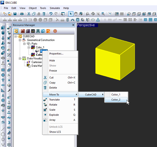
| − | You can move objects from one color to another in | + | You can move objects from one color to another in CubeCAD. You can also move objects from CubeCAD to other modules or among different modules. To transfer an object from its current color group to another color group, first select it in the Project Workspace and right click on its surface to open the contextual menu. Select '''Move To''' from the contextual menu. This menu item opens up to a number of submenus that include CubeCAD and possibly the names of some other [[EM.Cube]] modules. Each submenu leads to yet other submenus that contain the names of all the object groups that are available for object transfer. For instance, if CubeCAD has three color groups, color_1, color_2, color_3, you will see submenus like''' Move To [[File:larrow_tn.png]] CubeCAD [[File:larrow_tn.png]] Color_1''', '''Color_2''' or '''Color_3'''.Select the desired object group to transfer the selected object to. The transferred object's name is removed from its original color group and is added to the new color group. The color of the transferred object also changes to that of the new color group. In exactly the same way, you can transfer any object from its current group in any module to any other object group in any other module as long as it is listed in the '''Move To''' submenus. |
| − | You can also transfer objects from the Navigation Tree. When you import external CAD objects, they are always imported into | + | You can also transfer objects from the Navigation Tree. When you import external CAD objects, they are always imported into CubeCAD initially. Then, you have to move them to the right module. In such cases, you can select one of more object names on the Navigation Tree and right click on the highlighted selection to access the '''Move To''' submenus in the contextual menu. If you have highlighted a multiple selection using the '''Ctrl''' or '''Shift''' keys, remember to keep holding those keys down when right clicking; otherwise, you will lose the selection. |
[[File:moveobject_new.png|500px]] | [[File:moveobject_new.png|500px]] | ||
Revision as of 21:36, 27 August 2016
An Intuitive 3D Parametric CAD Modeler Shared By All EM.Cube Computational Modules
| |
Contents
- 1 CubeCAD in a Nutshell
- 2 CubeCAD Features at a Glance
- 3 Constructing Physical Structures Using Standard Geometric Objects
- 4 Creating New Objects
- 4.1 Drawing CAD Objects in the Active Color Group
- 4.2 The Property Dialog & Object Parameter Types
- 4.3 Modifying Objects Using Edit Handles
- 4.4 Using the Grid & Work Planes
- 4.5 Object Snap Points & EM.Cube's Snap Modes
- 4.6 Drawing New Objects Using Other Objects' Snap Points
- 4.7 Setting Up Quick Standard Work Planes
- 4.8 Setting Up an Arbitrary Work Plane
- 5 Object Operations & Transformations
- 6 Importing & Exporting CAD Models
CubeCAD in a Nutshell
CubeCAD is a comprehensive, parametric, 3D CAD modeler along with integrated mesh generation, data processing and visualization capabilities and a powerful Python scripting environment. A highly streamlined visual interface literally puts all of CubeCAD's features at your fingertips. With the click of buttons, you can build complex 3D models and structures in seconds using a large variety of intuitive mouse-based object creation and transformation tools. Import and export of standard CAD formats allow for native construction of complex geometries along with the ability to fly in external CAD models with utmost ease. CubeCAD also features an extensive library of mathematical functions that can be used for construction of new geometries and data or post-processing of existing data. CubeCAD allows you to visualize simulated, measured or imported 3D data in a variety of formats and overlay them on your CAD structures.
All of EM.Cube's computational modules use CubeCAD together with individually customized navigation trees as their graphical user interface and geometry definition utility. Learning CubeCAD is therefore the gateway to learning all the other modules. Once you have mastered the basics of CubeCAD, using the other modules will be very straightforward.
CubeCAD Features at a Glance
Geometric Features
- Native Solids: Box, cylinder, cone, pyramid, sphere, ellipsoid, torus, and polymesh solids (generalized polyhedra)
- Native Surfaces: Rectangular strip (or loop), circle strip (or ring), radial strip, ellipse strip, spiral strip, triangle strip, taper strip (with exponential transition), regular polygon, polystrip, NURBS strip, polymesh surfaces, equation-based, grid-based and data-file-based surfaces
- Native Curves: line, polyline, NURBS curve, circle, super-quadratic curve, parabola, hyperbola, spiral curve, helix, and equation-based Cartesian, polar and parametric curves and grid-based and data-file-based curves
- Easy mouse-based object creation and real-time editing with preview
- Translate, rotate, scale, mirror and link operations
- Boolean (union, subtract and intersect) operations and composite objects with access to constituent objects' properties
- Explode solids into surfaces and surfaces into curves
- Build 3D arrays of objects with dynamic editing and access to parent objects' properties
- Extrude, loft or revolve faces/surfaces and edges/curves and edit the parent objects dynamically
- Skin between multiple faces/surfaces and bridge between multiple edges/curves
- Discretize solids and surfaces into polymesh objects with regular or structured triangular cells
- Polygonize surfaces and curves
- Fit spline curves onto polylines and smooth surfaces onto polymesh surfaces
- Fillet sharp corners and polylines
- Sweep curves into strips, pipes or rail surfaces along curves
- Fill closed curves to create planar objects
- Merge or sew curves
- Adaptive grid with local view rotation
- Snap to objects, nodes, edges/curves or faces/surfaces
- Arbitrary work planes for sketching
Parametric Modeling
- Define variables to relate and control CAD object properties
- Constrained variables with arbitrary mathematical expressions including random variables
- Continuous, discrete or mixed parametric spaces
- Dynamic update and parametric editing
- Dry runs for sanity check
- Object links with arbitrary local offsets and rotation angles
- Object connections with persistent local coordinate systems
- Multiple dependency link chains
CAD Model Import & Export
- STEP import/export
- IGES import/export
- STL import/export
- DEM import
- Shapefile import
- DXF export
- Mesh data import/export
Data Generation & Processing
- Spreadsheet view of data with data processing features
- Import/export of data into spreadsheets
- Hundreds of mathematical functions for data processing
- User defined functions and expressions
- Statistical analysis of data
- Differentiation, integration, discrete Fourier transform and linear regression of data
- Data generator utility for creation of 3D data of Cartesian, spherical and mesh types
Data Visualization
- 3D complex data surfaces defined over triangular meshes with magnitude, phase and 3D vector plots
- 2D complex uniform and non-uniform data planes with magnitude, phase and 3D vector plots
- 3D complex polar/spherical angular data patterns
- Vectorial data surfaces and planes with individual X, Y, Z and total plots
- Extensive graphing capability (Cartesian, polar, Smith chart, bar chart, polar stem chart, etc.) with dynamic editing
Constructing Physical Structures Using Standard Geometric Objects
Variety of EM.Cube's Native Object Types
In EM.Cube, objects are generally categorized into four types: solids, surfaces, curves and points. A Point is a dimensionless object that is represented by a set of coordinates (x,y,z). Curves are one-dimensional objects, whose length can be measured. The simplest curve object is a (straight) line. Surfaces are two-dimensional objects whose surface area can be measured. A surface is usually characterized by a number of edges that enclose the object's area. The edges meet at vertices or nodes. The simplest surface object is a rectangle strip, which has four edges and four vertices. Solids are three-dimensional objects whose volume can be measured. A solid is usually characterized by a number of faces that enclose the object's volume. Faces meet at edges and edges meet at vertices or nodes. The simplest solid object is a box, which has six faces, twelve edges and eight vertices. In addition to the specific standard object types, there are generic curve objects, generic surface objects and generic solid objects. Most external CAD objects are imported as objects of the generic type.
In view of the drawing process and geometrical properties, objects can also be divided into two groups: Dimensional objects and Nodal objects. A dimensional object is characterized by a local coordinate system (a center and local X-, Y- and Z-axes) and a number of dimensional parameters such as length, width, height, radius, etc. Examples of dimensional objects are box, sphere, rectangular strip, line, helix, etc. EM.Cube provides a diverse list of native parameterized dimensional objects in all the three categories of curves, surfaces and solids. A nodal object is characterized by a set of points (nodes). EM.Cube's nodal objects include Polystrip, Polyline, NURBS Strip, NURBS Curve and Polymesh objects.
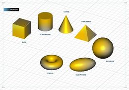
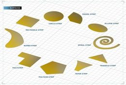
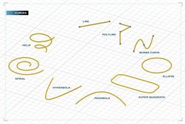
CubeCAD provides a diverse set of standard objects that are fully parameterized. In addition to the center coordinates and rotation angles, these objects have a variety of dimensional parameters that are used to set and control their size and geometrical shape. More complex objects can be created by editing and combining these basic shapes. Objects can be created by clicking on one of the object buttons on the Object Toolbar or from the Object > Solid, Object > Surface, or Object > Curve menus. Once an object tool is selected, left click anywhere on the work plane to draw the object. The following table show a list of EM.Cube's standard solid, surface and curve objects:
Local Coordinate System
EM.Cube provides a number of different coordinate systems. The two most important ones are the World Coordinate System (WCS) and the Local Coordinate System (LCS). Every object has a Local Coordinate System that determines the location of the object in the world coordinate system and its orientation, i.e., its rotation angles with respect to the world principal axes. The center of the local coordinate system is the most important characteristic point of an object. The position of the LCS center varies among different object types. For example, the LCS center of a box is the center of its bottom face, while the LCS center of a sphere is its true geometrical center. The LCS has three local X-, Y-, and Z-axes. For most objects, these axes line up with the object's natural axes. For example, the local Z-axis of a cylinder or a cone is always aligned along its geometrical axis. When you draw a new object, its LCS axes are aligned along the principal world axes by default. After you rotate an object, its LCS axes are no longer aligned with the principal world axes.
When you start the EM.Cube application, you will only see the world X- and Y-axes in the Project Workspace. A small trident icon at the lower left corner of the workspace also shows the world coordinate system at all times. There are many instances when the relative orientation of objects with respect to one another and their positive or negative directions are very important. In such cases, making the LCS of objects visible would be very useful. You can enable the local coordinate system of an object by selecting it, right clicking on the surface of the object or right clicking on its name in the Navigation Tree and selecting Show LCS from the contextual menu. This will display the red, green and blue local X-, Y- and Z-axes of the objects in dashed lines. To disable the LCS, select Hide LCS from the contextual menu of that object.
General Drawing Rules
By default, when you draw a new object, its property dialog appears at the lower right corner of main Window, and EM.Cube's object edit mode is enabled. This means that you can edit the newly drawn object at this time. After the drawing is completed, the mouse cursor changes to its "Normal" arrow shape. Besides the default "Draw & Edit" mode, EM.Cube provides another drawing modes called "Persistent Draw". In this persistent mode, after you complete the drawing of an object, the mouse cursor does not return to "Normal" and stays in the drawing mode. You can continue drawing more objects of the same type as many as you like. Switching the drawing mode is done from the User Preferences Dialog, which can be accessed from Edit Preferences... In the "Drawing Mode" section of the Objects tab of this dialog, select the radio button labeled Persistent Draw. In this mode, you will still see the object's property dialog at the lower left corner of Main Window. You can hide this dialog by unchecking the box labeled Display Properties.
 |
Glossary of Standard Objects
![]() Learn more about CubeCAD's Standard Geometric Objects.
Learn more about CubeCAD's Standard Geometric Objects.
| Standard Solid Objects | Standard Surface Objects | Standard Curve Objects |
|---|---|---|
|
|
|
Organizing Objects in Color Groups
CubeCAD's Navigation Tree groups and organizes objects using a hierarchical system. Located at the top of the Navigation Tree and under the CubeCAD icon are two main groups: Geometrical Construction and Data Visualization. Under Geometrical Construction, you create or import and manage CAD objects. Under Data Visualization, you create or import and display 3D representations of real, complex, scalar or vector data in a variety of formats. The Data Visualization group and its usage will be discussed later in this manual. The next sections of the manual will present a detailed discussion of CAD objects, their creation, transformation and management.
Geometrical Construction (represented by the ![]() icon) contains the Parts that form a structure. Parts (represented by the
icon) contains the Parts that form a structure. Parts (represented by the ![]() icon) contain all the native objects that you draw in CubeCAD's project workspace as well as all the CAD objects that your import from supported external CAD files. Parts are made up of one or more colors. CubeCAD's objects are grouped by Color represented by the
icon) contain all the native objects that you draw in CubeCAD's project workspace as well as all the CAD objects that your import from supported external CAD files. Parts are made up of one or more colors. CubeCAD's objects are grouped by Color represented by the ![]() icon. You can create many colors and add objects to each color group. All the objects belonging to a Color literally share the same color or texture. When you start EM.Cube for the first time and draw a new object in CubeCAD, a default color named "Color_1" is immediately created to hold your new object. The default color is grey. You can change the name, color or texture of this default group or add new color groups. To create a new Color, right click on the Parts item of the Navigation Tree and select Insert New Color.... A dialog opens up that contains a default name for the new color. Accept the default name or type in a new name for the new color group.
icon. You can create many colors and add objects to each color group. All the objects belonging to a Color literally share the same color or texture. When you start EM.Cube for the first time and draw a new object in CubeCAD, a default color named "Color_1" is immediately created to hold your new object. The default color is grey. You can change the name, color or texture of this default group or add new color groups. To create a new Color, right click on the Parts item of the Navigation Tree and select Insert New Color.... A dialog opens up that contains a default name for the new color. Accept the default name or type in a new name for the new color group.
To delete a color group, right click on its name in the Navigation Tree and select the Delete item from the contextual menu. Note that once a color is deleted, all the objects belonging to that color group are also deleted. You can delete all the color groups at once by right clicking on the Parts item of the Navigation Tree and selecting Delete All Colors from the contextual menu.
Transferring Objects Among Different Groups or Modules
You can move objects from one color to another in CubeCAD. You can also move objects from CubeCAD to other modules or among different modules. To transfer an object from its current color group to another color group, first select it in the Project Workspace and right click on its surface to open the contextual menu. Select Move To from the contextual menu. This menu item opens up to a number of submenus that include CubeCAD and possibly the names of some other EM.Cube modules. Each submenu leads to yet other submenus that contain the names of all the object groups that are available for object transfer. For instance, if CubeCAD has three color groups, color_1, color_2, color_3, you will see submenus like Move To ![]() CubeCAD
CubeCAD ![]() Color_1, Color_2 or Color_3.Select the desired object group to transfer the selected object to. The transferred object's name is removed from its original color group and is added to the new color group. The color of the transferred object also changes to that of the new color group. In exactly the same way, you can transfer any object from its current group in any module to any other object group in any other module as long as it is listed in the Move To submenus.
Color_1, Color_2 or Color_3.Select the desired object group to transfer the selected object to. The transferred object's name is removed from its original color group and is added to the new color group. The color of the transferred object also changes to that of the new color group. In exactly the same way, you can transfer any object from its current group in any module to any other object group in any other module as long as it is listed in the Move To submenus.
You can also transfer objects from the Navigation Tree. When you import external CAD objects, they are always imported into CubeCAD initially. Then, you have to move them to the right module. In such cases, you can select one of more object names on the Navigation Tree and right click on the highlighted selection to access the Move To submenus in the contextual menu. If you have highlighted a multiple selection using the Ctrl or Shift keys, remember to keep holding those keys down when right clicking; otherwise, you will lose the selection.
Moving objects from their current color group to other color or other EM.CUBE modules.
Creating New Objects
Drawing CAD Objects in the Active Color Group
At any time, only one color group of the Navigation Tree is active, where all the newly drawn objects are placed and listed. CubeCAD displays the active color's name in bold. When you start EM.Cube for the first time and draw a new object in CubeCAD, a default color named "Color_1" is immediately created and set as the active color. Every time you create a new color, it is set as the active color. To change the active color, right click on the name of a color and select Activate from the contextual menu. New objects will now be added under the new active color.
To draw an object in EM.Cube, click one of the many Object buttons in Object Toolbar and start drawing a new object in the project workspace. Alternatively, you can call on any object creation tool through one of Menu > Object > Solids, Surfaces or Curves submenus. Once an object creation tool is selected, the shape of the cursor changes to a cross, signifying that EM.Cube is in object creation mode. Left click anywhere in the Main Window to draw an object of the selected type. While the new object is being drawn, a property dialog appears on the lower right corner of the screen. Also, a small Help Tip window opens up on the upper right corner of the screen that guides you through the drawing process. The property dialog allows you to customize the new object's dimensions and other parameters. The entered values for lengths are always in the currently selected project units and angles are measured in degrees.
The Property Dialog & Object Parameter Types
Each CubeCAD object has a number of properties that are characteristic to the object type and are listed in its Property Dialog. When you draw a new object, its property dialog opens up while you are drawing it. After the new object has been created, its properties dialog remains open until you close it. To open the property dialog of an object, double click on the object's surface in the project workspace or first select it and then right click on its surface and select Properties... from its contextual menu. You can also open an object's property dialog by right clicking on its name in the navigation tree and selecting Properties... from the contextual menu. The diagram on the right shows the property dialog of a Box object.
All object property dialogs share some common fields:
- Object Label
- Object Linkage information
- Spatial information such as LCS center coordinates and rotation angles
- Dimensional properties such as length, width, height, radius, etc. (this applies to dimensional object types like box, rectangle strip, line, etc.)
- Nodal information such as node indices and coordinates (this applies to nodal object types like polyline, polystrip, etc.)
CAD objects are characterized by their Local Coordinate Systems (LCS). Spatial information contains two sets of information: LCS Center– the X-, Y-, and Z-coordinates of the origin of the local coordinate system, and LCS Rotation – the right-sense rotation angles of the object about the X, Y, and Z-axes before the object is translated to the specified base center. As you will see later, objects in CubeCAD can be linked to each other. The linkage information part of the property dialog shows whether an object is linked to another "parent" object and if so, in what manner. The type and number of property fields are unique to each native CubeCAD object. The box object, for instance, contains Length, Width and Height values along with Lock Base and Cap Ends check boxes.
Modifying Objects Using Edit Handles
Once you finish drawing an new object in the default "Draw & Edit" mode or when you open the property dialog of an object, EM.CUBE enters its "Object Edit Mode". In this mode, a number of small red balls appear on the object that are called "Edit Handles" and are located at some of the object's snap points The exact number of edit handles varies among the different object types. For example, a box has six edit handles, one at the center of each face. A rectangular strip has four edit handles, one at the midpoint of each edge. A line has two edit handles at its two ends. In the "Object Edit Mode", you can grab an edit handle and drag it with the mouse to change the size or shape of an object. By grabbing we mean first hovering on the handle (mouse-over) to highlight it and then clicking the left mouse and dragging it around. In dimensional objects, grabbing an edit handle usually changes a certain length or an angle. In nodal objects, grabbing an edit handle changes the position of a node.
Using the Grid & Work Planes
CubeCAD is a full 3D CAD environment that allows you to move your mouse to any arbitrary point in the three-dimensional coordinate space. A work plane is the plane on which the mouse cursor is located and moves freely around. When you start the EM.Cube application, the mouse always moves on the XY plane, meaning that the XY plane is your default work plane. In addition, EM.Cube shows the project workspace's grid, and its "Snap-to-Grid" mode is enabled by default. As you move the mouse around, it snaps to the grid points. This provides a convenient way to draw objects with precise dimensions and at precise locations. The coordinates of the current location of the mouse are reported in the Status Bar.
![]() Click here to learn more about EM.Cube's Grid.
Click here to learn more about EM.Cube's Grid.
Using the View Toolbar, you can easily change the work plane to any of the three principal coordinate planes:
When the work plane is set to the XY plane, the Z-coordinate of the mouse is fixed and equal to zero.
When the work plane is set to the YZ plane, the X-coordinate of the mouse is fixed and equal to zero.
When the work plane is set to the ZX plane, the Y-coordinate of the mouse is fixed and equal to zero.

Object Snap Points & EM.Cube's Snap Modes
Every EM.Cube object has a number of Snap Points that are strategically located on it for a variety of purposes. Snap points are very important in EM.Cube. Many CAD operations and object transformation tools work based on snap points. Each solid object in general has a number of faces, edges and vertices (or nodes).A surface object normally has one face, a number of edges and vertices. A curve usually has one edge and two or more nodes. In most EM.Cube objects, the centers of faces, the midpoints of edges and the nodes or vertices constitute the snap points of that object. For example, a Box has six face snap points, twelve edge snap points and eight vertex snap points.
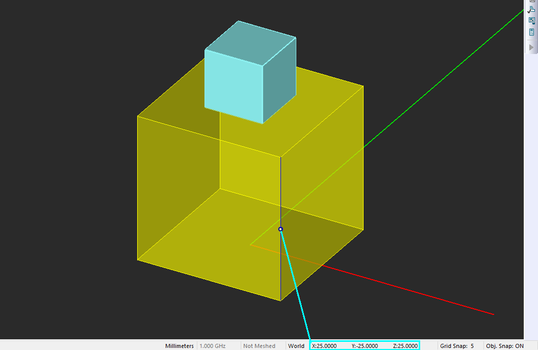
When you start the EM.Cube application, it is by default in the Snap to Object mode. This means that when you move the mouse over the surface of an object (without clicking), the object becomes highlighted with a translucent shade of the selection color (yellow by default). If the object is a solid, you can see inside of the object. If you get close to a vertex, the mouse snaps to that vertex. Similarly, if you get close to the middle of an edge, the mouse snaps to the edge's midpoint. Or on a face, the mouse snaps to the center of that face. When the mouse snaps to an object's snap point, a small circle in the complementary selection color (dark blue by default) appears on the snapped point. We refer to this as a "Mouse-Over" state. At this state, the Status Bar reports the coordinates of the snapped point. If the snapped point is the center of a face, the perimeter of that face is also highlighted in the same color. If the snapped point is the midpoint of an edge, that edge is also highlighted. If you move the mouse slightly away from the snapped point, it unsnaps and starts moving freely on the work plane until it snaps again to another available snap point.
Sometimes, highlighting objects simply by mouse-over may turn out to be rather bothersome especially in dense structures. In this case, you can turn off the "Snap to Object" mode. To do so, double click on the small window at the right end of the Status Bar, which reports the current state of object snap mode. This will cycle through the different objects snap mode. Continue double clicking until you get Obj. Snap: OFF. Double clicking one more time will lead to Obj. Snap: ON. You can also enable the Snap to Object mode using the keyboard shortcut O. The illustration below depicts several objects and their corresponding snap points.
Accessing all the available snap points of an object can be quite tricky. When the mouse hovers over an object, you can more easily access the hidden snap points (those associated with the hidden faces or edges or corners) by holding down the keyboard's Ctrl Key and positioning the mouse close to the desired point.
| |
Snap to object always has priority over snap to grid. In other words, the mouse jumps from a grid node point immediately to the closest object snap point. |
In addition to Snap-to-Object mode, EM.Cube provides three more snap modes:
- Snap to Node Mode: This mode allows you to precisely snap the cursor to any vertex or node of a given object. In other words, it snaps to singular points on the object.
- Snap to Edge Mode: This mode allows you to snap the cursor to all the points on any edge or along a curve object. Using the Status Bar you can read the coordinates of any point on any curve. Note that if the "Snap to Grid" is also enabled at the same time, the cursor will snap to a point along the edge or curve that has the shortest distance from closest grid point.
- Snap to Face Mode: This mode allows you to snap the cursor to all the points on any face or any surface object. Using the Status Bar you can read the coordinates of any point on any irregular or curved surface. Note that if the "Snap to Grid" is also enabled at the same time, the cursor will snap to a point on the face or surface that has the shortest distance from closest grid point.
The "Snap to Grid" mode is controlled independent of the other snap modes. "Snap to Object" is the default mode of EM.CUBE. To switch to one of the other three snap modes, double click on the box displaying Obj Snap: ON on the Status Bar, and cycle through these modes in the order: Snap: NODE, Snap: EDGE, Snap: FACE, and Snap: OFF. The last mode completely disables any object snapping. You can enable or disable all the object snap modes from the View Menu by selecting View ![]() Snap
Snap ![]() Snap to Object, Snap to Node, Snap to Edge, or Snap to Face. You can check or uncheck these menu items. When there is no check mark in front of one the four snap modes, then the object snapping is disabled. From this menu, you can also enable or disable the "Snap to Grid" mode. To do so, select or deselect View
Snap to Object, Snap to Node, Snap to Edge, or Snap to Face. You can check or uncheck these menu items. When there is no check mark in front of one the four snap modes, then the object snapping is disabled. From this menu, you can also enable or disable the "Snap to Grid" mode. To do so, select or deselect View ![]() Snap
Snap ![]() Snap to Grid.
Snap to Grid.
| |
Mouse-over and highlighting objects works only in one of the four object snap modes. |
Snapping to an object edge and viewing the mouse coordinates in Status Bar.
Drawing New Objects Using Other Objects' Snap Points
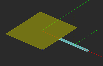
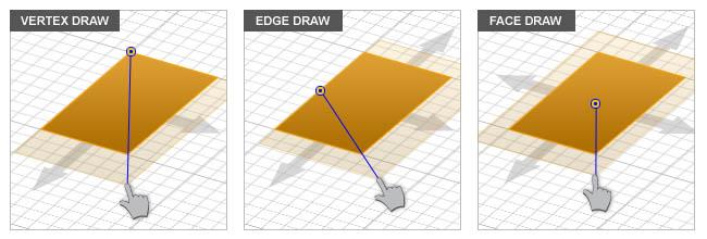
You can use the snap points of existing objects in the project workspace to draw new objects. This feature often turns out to be very convenient and useful. For example, you can draw a new box object out of the center of one of the six faces of another box object. Or you can draw a new rectangle strip object out of the center of one of the four edges of another rectangle strip object. To do so, select the desired drawing tool and hover the mouse over the snap point of another object where you want to place the new object. Once the existing snap point is highlighted and selected, proceed to draw the new object. The figures on the right show the procedure for drawing new objects using the snap points of existing objects.
When you draw a box, cylinder, cone or pyramid from the center of the face of another object, EM.Cube indeed establishes a temporary work plane at the selected face. The local coordinate system (LCS) of the new object is set up at the center of the selected face. When you finish the drawing process, the temporary work plane is eliminated, and the original work plane before the new drawing is re-established. When you draw a rectangle strip from an edge of another object, the edge-based drawing mode is enabled for the new rectangle strip. The "Lock Base" check box of the new rectangle strip is unchecked along the local direction normal to the selected edge.
Setting Up Quick Standard Work Planes
Setting the right work plane is very important for the following reasons:
- Surfaces and curves are always drawn on the active work plane. As for Helix, its turns are parallel to the active work plane while its axis is normal to that plane.
- The LCS of solid objects is drawn with local X- and Y-axes in the active work plane and the local Z-axis normal to it. This means that the bottom base of all boxes, cylinders, cones and pyramids are always drawn on the active work plane. Spheres, ellipsoids and tori are always drawn centered on the active work plane.
EM.CUBE's Work Plane tool lets you set up arbitrary work planes anywhere in the Project Workspace. In most cases, you may simply need to set up your work plane at an offset distance from one of the three principal XY, YZ or ZX planes. For example, in layered structures, it is convenient to set up the work plane at the interface between two layers. EM.CUBE provides an easier way to set up a work plane that is parallel to XY, YZ or ZX planes. For this purpose, you need to target an object snap point. Mouse-over any object in the Project Workspace and highlight one of the snap points of that object. Then, type X, Y, or Z on your keyboard. This will establish a new work plane centered at the snapped point and parallel to the YZ, ZX or XY planes, respectively. These are simply keyboard shortcuts to quickly establish a standard work plane. Once the new work plane appears, you can open the Work Plane Dialog to changes its parameters including location, orientation and appearance.
Setting up a quick standard work plane parallel to YZ plane using the keyboard shortcut X.
Setting Up an Arbitrary Work Plane
Sometimes you may want to create objects at a certain distance away from one of the three principal work planes. In some other cases, you may want to set up an arbitrary work plane. EM.CUBE lets you set up an arbitrary work plane different than the three principal coordinate planes. Before learning to do this, let's first consider the different ways you can define an arbitrary plane in EM.CUBE:
- Any planar face of a solid or surface object defines a unique plane.
- A point and a vector uniquely define a plane.
- Any three non-collinear points in space define a unique plane.
EM.CUBE's Work Plane Tool lets you define any arbitrary work plane using one of the above three methods. Click on the Work Plane ![]() button in the View Toolbar, or select Menu
button in the View Toolbar, or select Menu ![]() View
View ![]() Work Plane
Work Plane ![]() Arbitrary Plane, or use the keyboard shortcut W to enable EM.CUBE's "Work Plane Mode". The Work Plane Dialog opens up at the lower right corner of the screen. Below are three different ways that you can define a new arbitrary work plane:
Arbitrary Plane, or use the keyboard shortcut W to enable EM.CUBE's "Work Plane Mode". The Work Plane Dialog opens up at the lower right corner of the screen. Below are three different ways that you can define a new arbitrary work plane:
- Mouse-over any object in the Project Workspace and click on a face snap point, i.e. the center of a highlighted planar face. A new work plane appear overlaid on the selected face.
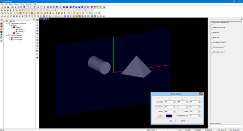
- Or while you are in one of the three principal Xy, YZ or ZX work planes, click any blank point and drag the mouse. A semi-translucent plane perpendicular to the current work plane is drawn and displayed in the Project Workspace. The normal plane follows the movement of the mouse as you drag it. Once you reach the desired orientation, double click or type the keyboard's' Enter Key' to finalize the new work plane.
- Or click on any blank point and select two more points anywhere in the workspace (including other objects' snap points). A new work plane is established that passes through the three selected points.
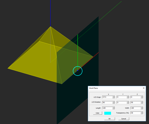
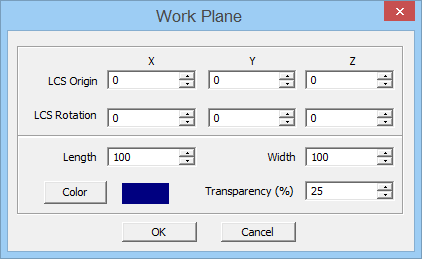
In all the three cases above, a translucent plane appears showing the location and orientation of the new work plane. The transverse axes (local X and Y axes) of the new work plane are displayed in red and green colors, respectively. A new "User Coordinate System (UCS)" is established on the new work plane. In the Work Plane Dialog, you can see the world coordinates of the center of the UCS and its rotation angles with respect to the project's world coordinate system (WCS). From this dialog you can change both the center coordinates and the rotation angles. This will change the location and orientation of the new arbitrary work plane. Once you are content with the location and orientation of the new work plane, you can also change its visible size. Note that the visible size of the work plane is purely for visualization purposes; otherwise, the work plane has infinite extents. You can change both Length and Width of the work plane separately. You can also change the Color and Transparency level of the work plane.
EM.CUBE's Work Plane dialog.
Once a new work plane is established, the mouse will be bound to that plane. In other words, the cursor will move freely on the surface of the new work plane. The Status Bar now reports the "User Coordinates" of the cursor position as opposed to its "World Coordinates". The status bar also shows the word User in front of these coordinates. You can switch back to the world coordinates at any time by double clicking the word User, which changes it to World. Double clicking once again toggles the state back to the user coordinates. Any object that you draw on the new work plane will have its local X and Y-axes on this plane, and its local Z-axis normal to the plane. While a non-principal work plane is active, you can always summon its dialog and change its properties. To do so, click on the Work Plane button in the View Toolbar, or select Menu ![]() View
View ![]() Work Plane
Work Plane ![]() Arbitrary Plane, or use the keyboard shortcut W.
Arbitrary Plane, or use the keyboard shortcut W.
| |
A new work plane will stay in effect until to switch to one of the three principal work planes. |
Setting up an arbitrary work plane in the project workspace.
Object Operations & Transformations
Changing Object Visibility, Color and Texture
You can hide and show individual objects, color groups and even the entire parts. This can be very helpful when you work with structures that contain a significant number of parts containing large and small objects in close proximity to one another. Hiding individual objects or color groups allows you to focus on the points of interest within your structure. To hide or show individual objects or color groups or the entire parts, right click on the name of the object, color or the "Parts" item in the Navigation Tree and select Hide or Show from the contextual menu.
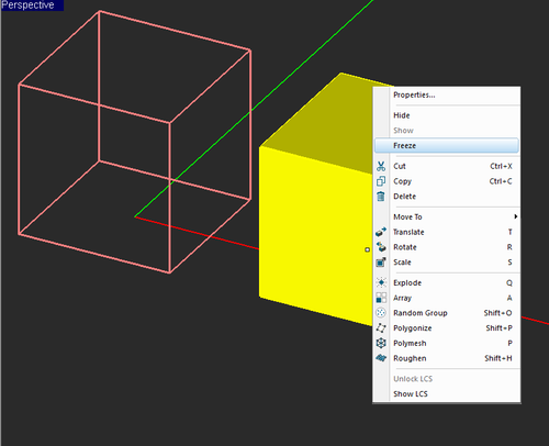
You can also freeze individual objects or color groups. When an object is frozen, EM.CUBE shows only a wire-frame of that object in its own color. You cannot mouse-over, highlight or select a frozen object in the Project Workspace. To freeze an individual object or a color group, right click on its name in the Navigation Tree and select Freeze from the contextual menu. To unfreeze a frozen object or color group, right click on its name in the Navigation Tree and remove the check mark already places before the Freeze item in the contextual menu.
| |
You cannot highlight "frozen" objects by mouse-over. |
Freezing objects in the Project Workspace.
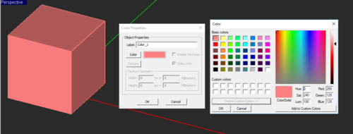
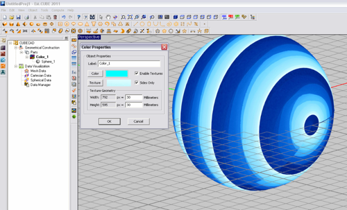
You can change the default color by clicking the button labeled Color to open up the standard color palette. You can edit an existing color through its Property Dialog. Right click on the name of a color group on the Navigation Tree and select Properties... This opens up the Property Dialog of the selected color. You can change the name, color or texture of the group just as explained later.
By default, the color groups do not have a texture. You can replace a solid color with a texture that is generated from a bitmap. First, you have to check the box labeled Texture. This enables the texture section of the dialog. Click the Texture button to invoke Windows' Open Dialog. The file type is set to "Bitmap Files (*.bmp)". Use the Browse button to find the desired bitmap file and open it. Next, you have to define the texture mapping scale. On the objects, the texture will show up as tiles of the imported bitmap. In the Texture Geometry section of the dialog, two boxes show the Width and Height of the bitmap in pixels. You need to map these onto the desired tile width and height in project units. These settings determine how many texture tiles appear on each object given its dimensions. If large values are set for the tile width and height, partial bitmap will show up on the objects. You also have the option to apply the texture to the Side Only by checking the related box.
Changing the color of a color group.
Setting the texture of a color group.
Selecting, Cutting, Copying, Pasting & Deleting Objects
In order to modify or apply CAD operations to objects, they must first be selected. The navigation tree provides a convenient interface that allows you to select one or more objects. The simplest way to select an object is to click on its surface in the project workspace. When an object is selected, its color changes to the "Selection Color" (yellow by default). When you select an object in the project workspace, its name on the navigation tree is highlighted in the selection color. Alternatively, you can select an object by clicking on its name in the navigation tree. In that case, the selected object's name is highlighted in the navigation tree, and the object itself is highlighted in the selection color in the project workspace. To deselect a selected object, simply click on any blank point in the project workspace.
You can select more than one object at a time. There are several ways to do a multiple selection. The simplest way is to select the first object in the project workspace. Then, while holding the keyboard's Ctrl key down, click on the second and subsequent objects that you want to add to the selection. You can follow the same procedure in the navigation tree. While holding the keyboard's Ctrl key down, click on the names of all the objects you want to select in the navigation tree. In a "Range Selection", you can select a sequential set of objects belonging to the same color group. First, you click on the name of the first object in the navigation tree. Then, while holding the keyboard's Shift key down, you click on the name of the last object to be selected. All the objects whose name are listed between those two objects are also selected and highlighted.
Cut, copy, paste and delete are some of the most common edit operations. As in many other Windows applications, you can cut an object (from the workspace) and hold it in the Windows' clipboard until you paste it back to the workspace. You can also copy an object and paste it back to the workspace. Deleting an object removes it forever from the project workspace, although you can undo your delete operation.
The simplest way to cut, copy, paste o delete an object or a selection of objects is using the keyboard shortcut Ctrl+X, Ctrl+C, and Ctrl+V, respectively, or use the keyboard's Delete key. You can also use the Cut, Copy, Paste and Delete buttons of System Toolbar or similar items of the Edit Menu. The right-click contextual menu of objects in the project workspace or on the navigation tree yet provide additional ways for cutting, copying, pasting and deleting objects.
When you paste an object or a selection of objects to the project workspace, CubeCAD allows you to place the pasted object(s) in any arbitrary location right away. First, a wire-frame of the pasted object(s) appears in the workspace, which you can drag around with the mouse. Wherever in the workspace you click the mouse, the pasted object(s) will be dropped. A dialog titled "Place" appears on the lower right corner of the screen that shows the current coordinates of the mouse point (as you drag it) in three X-, Y- and Z-coordinate boxes labeled Destination as well as three X-, Y- and Z-coordinate boxes labeled Vector. The vector coordinates show the Cartesian components of the displacement vector pointing from the original position of the cut or copied object(s) to the current mouse position. As you drag the mouse around, all these values get updated continuously. You can fine-tune the final location of your pasted object using either of the two coordinate sets.
Glossary of EM.Cube CAD Tools
EM.Cube provides a large number of CAD tools that translate, rotate, scale and perform more complex geometric transformations on one or a selection of several objects.
![]() Click here to learn more about the various types of CAD Tools & Geometric Transformations.
Click here to learn more about the various types of CAD Tools & Geometric Transformations.
Importing & Exporting CAD Models
Importing Objects from External Files
Building complex simulations often requires one to import CAD objects from external files. Currently, EM.Cube can read in the following file formats:
- STEP File (*.STEP or *.STP)
- IGES File (*.IGES or *.IGS)
- Stereolithography File (*.STL)
- Raw Triangles (*.RAW)
- Shape File (*.SHP)
- CUBIT Facet File (*.FACET)
- ASCII DXF File (*.DXF)
- Digital Elevation Map (DEM) File (*.DEM)
- Python File (*.PY)
To import an external file of one of the above formats, select Menu > File > Import... Once the standard Windows Open Dialog pops up, select the desired file extension from the dropdown list labeled "Files of type:". Then, select the desired file and click the Open button of the dialog. This opens another dialog that shows the progress of loading the imported file. You can abort the import process by clicking the Abort Translation button. You can also view a report of the process. All imported objects are listed under Color_1. From this group you can move them to other groups. In some cases, the imported object might already be organized in different colors or groups. In all file formats except for STL, solid objects are imported as EM.Cube's generic solids and surface objects are imported as EM.Cube's generic surfaces. From STL files, objects are imported as EM.Cube's native polymesh objects.
| |
You can import external CAD files only into CubeCAD. From here you can move objects to EM.Cube's other modules. |
Exporting Project Structure
You can save the structure that you build in EM.Cube to an external CAD file for later use or transfer to other applications. Currently, EM.Cube can write out the following file formats:
- STEP File (*.STEP or *.STP)
- IGES File (*.IGES or *.IGS)
- Stereolithography File (*.STL) - ASCII
- Stereolithography File (*.STL) - Binary
- CUBIT Facet File (*.FACET)
- DXF File (*.DXF)
- Python File (*.PY)
To export the project structure to an external file of one of the above formats, select Menu > File > Export... Once the standard Windows Save As Dialog pops up, select the desired file extension from the dropdown list labeled "Save as type:". Then, type in a name for the file and click the Save button of the dialog. This opens another dialog that shows the progress of writing the exported file. You can abort the export process at any time by clicking the Abort Process button.
Note that in the case of DXF export, all the surface CAD objects lying in the XY Plane or in any horizontal plane and only rectangular objects lying in the YZ or ZX planes or in any vertical plane parallel to these planes are exported. Curve and solid CAD objects are ignored during the export process.
Working with STL Models
Stereolithography files contain a tessellated (triangulated) representation of a structure. EM.CUBE treats STL files in a special way. You can export the project structure into a STL file in the form of a polymesh object. This is similar to writing the structure mesh data into a mesh data file of ".msh" extension. The project structure is tessellated using CUBECAD's triangular surface mesher of the Structured Type. EM.CUBE gives you two options for STL export: Binary STL and ASCII STL. The latter file is bigger in size. You can import STL files of both binary and STL types into EM.CUBE. STL models are imported as native polymesh objects. As a result, you can edit the imported objects and modify their various parameters arbitrarily. This is in contrast to importing files of other formats, which create solid and surface objects of the generic type. Once you import a STL file, you can change the mesh type of the imported object to the Regular Type. You can also decrease the Edge Length to obtain a higher resolution. Just like other polymesh objects, you can insert nodes on the faces and edges or delete nodes from the imported object.
CubeCAD's Surface Mesh
Mesh generation is an important part of computational engineering. A mesh is used to discretize a continuous geometry into a set of much simpler elementary cells or mesh "elements". Solid objects can be discretized into tetrahedral elements. Surfaces can be meshed using triangular cells. Curves can be discretized into polylines. As you will see in EM.CUBE's other modules, EM.CUBE provides a large number of diverse mesh generators. The accuracy of a numerical simulation often depends directly on the quality of the mesh. It is also important to be control the resolution of a mesh, namely, the size of mesh cells. Higher mesh resolutions normally lead to better accuracy of the numerical results.
Tetrahedral and surface triangular meshes are one of the most widely used mesh types in many different engineering disciplines. CUBECAD provides two types of mesh generation algorithms for discretizing objects. The first one generates a wire-frame surface triangular mesh of surface objects and a polyline mesh of curve objects. The solid objects are treated as closed surfaces and are discretized using a similar wire-frame surface mesh. in other words, objects of all types are meshed in some sort. The wire-frame mesh generator has two variations. The first algorithm generates a regularized mesh and attempts to create triangular cells of almost equal size. The second algorithm tries to create a structured mesh with cells of similar patterns. CUBECAD's other mesh generator generates a tetrahedral mesh for solid objects. Tetrahedral meshes are usually enormous in size. Note that surface and curve objects cannot be discretized using this type of mesh generator.
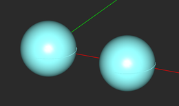
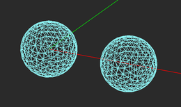
A sphere and its surface triangular and tetrahedral meshes.
Generating and Controlling the Mesh
You can generate a mesh of the structure in CUBECAD in one of the following three ways:
- By clicking the Show Mesh
 button of Compute Toolbar.
- By selecting Menu
 Compute
  Discretization
  Show Mesh.
- Using the keyboard shortcut Ctrl+M.
When the mesh is displayed in the Project Workspace, EM.CUBE's mesh view mode is enabled. In this mode, all the objects are discretized using the selected mesh generation algorithm and the meshes of all objects are displayed. In mesh view, you cannot mouse-over, select or edit any objects. The mesh view is for viewing purpose only. You can perform most of view operations such as zooming in and out using the mouse scroll wheel, rotating the view using the right mouse button RMB and panning the view using Shift+RMB. When EM.CUBE is in mesh view mode, the Show Mesh![]() button of Compute Toolbar remains depressed. To hide the mesh, exit the mesh view mode and return to the normal view mode, simply click the Show Mesh
button of Compute Toolbar remains depressed. To hide the mesh, exit the mesh view mode and return to the normal view mode, simply click the Show Mesh![]() button one more time to toggle its state, or press the keyboard's Esc Key (Escape), or select Menu
button one more time to toggle its state, or press the keyboard's Esc Key (Escape), or select Menu ![]() Compute
Compute ![]() Discretization
Discretization ![]() Show Mesh and remove the check mark in front of it.
Show Mesh and remove the check mark in front of it.
You can change the mesh type and the mesh resolution from the CAD Mesh Settings Dialog. Click the Mesh Settings![]() button of Compute Toolbar or select Menu
button of Compute Toolbar or select Menu ![]() Compute
Compute ![]() Discretization
Discretization ![]() Mesh Settings...In the dropdown list labeled Mesh Type you can select one of the three options: Regular Surface, Structured Surface or Tetrahedral. The mesh resolution is controlled by Edge Length which is expressed in project units. The default value of edge length is 10 units. This means that the default mesh features cells with a size of about 10 units. When you change the mesh type or resolution, you can see the effect using the Apply button if EM.CUBE is already in mesh view mode. After EM.CUBE generates a mesh, it saves its and uses it the next time you want to see the mesh. The mesh stays the same until you change its parameters. Sometimes, you may want to regenerate the mesh with the same current parameters. To do so, select Menu
Mesh Settings...In the dropdown list labeled Mesh Type you can select one of the three options: Regular Surface, Structured Surface or Tetrahedral. The mesh resolution is controlled by Edge Length which is expressed in project units. The default value of edge length is 10 units. This means that the default mesh features cells with a size of about 10 units. When you change the mesh type or resolution, you can see the effect using the Apply button if EM.CUBE is already in mesh view mode. After EM.CUBE generates a mesh, it saves its and uses it the next time you want to see the mesh. The mesh stays the same until you change its parameters. Sometimes, you may want to regenerate the mesh with the same current parameters. To do so, select Menu ![]() Compute
Compute ![]() Discretization
Discretization ![]() Regenerate Mesh.
Regenerate Mesh.
Saving Mesh Data to a File
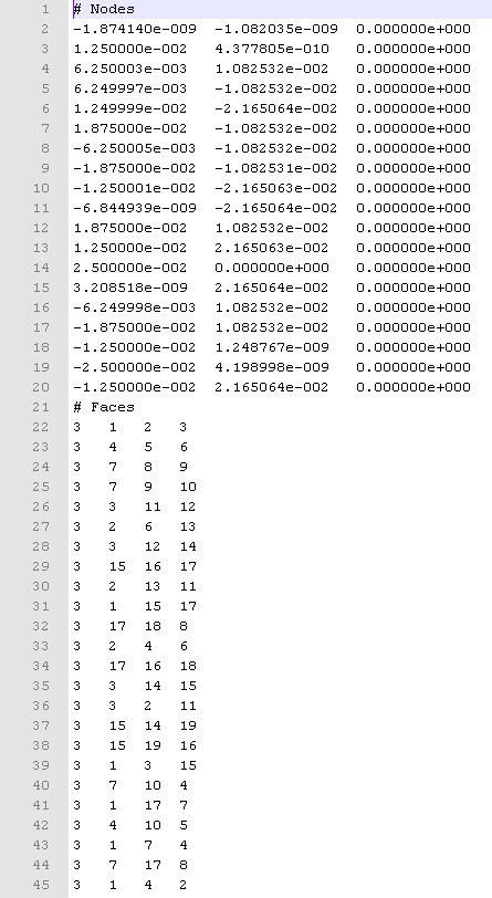
CUBECAD generates a triangulated mesh of surface and solid objects and a linearized or polygonal mesh of curve objects. The triangular surface mesh of surface and solid objects are equivalent to EM.CUBE's native polymesh objects while the polygonal mesh of curve objects are equivalent to polyline objects. The mesh data can be saved into an ASCII data file with a .msh file extension. The top part of this file contains coordinates of all the nodes involved in the mesh. Then comes the definition of the elements of faces. Each line defines the number of nodes in each element and the index of the nodes in the order presented in the previous node definition section. Thus, triangular elements (faces) have three node indices while the linear elements (bars)have two node indices.
Polymesh and polyline objects are already discretized and are not meshed again when EM.CUBE generates a mesh of the structure in the Project Workspace. As such, polymesh and polyline objects preserve their nodes as they are saved into a mesh file.
The mesh file representing a polymesh surface object.


