Importing RF Device Models
Multiport Network device, i.e. one-ports, two-ports, three-ports and four-ports, are all modeled based on their frequency-domain S-parameters. Most active and passive RF devices can be modeled as multipart networks. For example, RF diodes can be modeled as one-ports, while RF transistors (BJTs, JFETs, MOSFETs, and MESFETs) can be modeled as two-ports. Many semiconductor manufacturers publish S-parameter data sets for their RF devices. The manufacturer data sheets usually contain S-parameters in Mag/Phase format tabulated as a function of frequency expressed in GHz. On the other hand, you can model many passive devices such as filters, directional couplers, hybrids, etc. as multiport structures using full-wave electromagnetic simulators like EM.Cube. The port characteristics of such devices are typically written into data files as a function of frequency. A particular case of interest is transmission line components with complex geometries or material composition, for which RF.Spice does not provide any database models. as an example, consider the case of a "Finline" transmission line. In a finlike-based circuit, you may need one of more of the following general transmission line components:
- Open End
- Bend (right-angled or mitered)
- Step Junction
- Tee Junction (symmetric or asymmetric, possibly with a notch)
- Cross Junction (symmetric or asymmetric)
RF. Spice currently does not provide any models for finline components. However, you can use EM.Cube to analyze various finline structures over a frequency range of interest and generate S-parameter data sets for them.
RF.Spice allows you to import S-parameter-based models of RF devices from text files. Before describing how to import S-parameter data files, let us first discuss the format of the data files in more detail. S-parameter data files must have a ".TXT" file extension. These files must start with a ".model", a ".symbol" statement, and a format statement starting with the character "#". The model text file can have any number of comment lines at the beginning of the file or elsewhere. Comment lines are preceded by "*" or "!". All the text after these characters on the rest of the line will be ignored.
Format:
.model <model_name>
.symbol <symbol_name>
#<frequency_units> s <complex_data_format> r <reference_impedance_value>
freq s11 s21 s32 s12 s22 s32 s13 s23 s33
Example:
! This is an example of an RF BJT model based on measured S-parameters.
.model MyNewRFBJT
.symbol bjt_npn
#ghz s ma r 50
! GHz MAG ANG MAG ANG MAG ANG MAG ANG
0.500 0.6943 -122.1 4.977 105.7 0.0901 33.0 0.6170 -37.8
1.000 0.6470 -169.7 2.820 76.8 0.0975 23.3 0.4862 -45.5
1.500 0.6586 162.9 1.959 57.6 0.0978 25.6 0.4468 -54.5
2.000 0.6854 142.0 1.481 41.5 0.1055 32.2 0.4315 -65.1
2.500 0.7070 128.1 1.246 30.1 0.1175 37.7 0.4261 -75.5
3.000 0.7449 110.9 0.985 15.5 0.1475 41.9 0.4218 -93.3
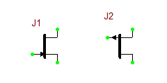
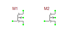
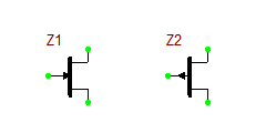
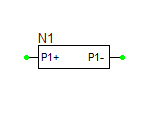
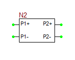
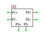
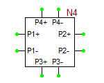
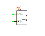
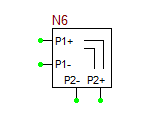
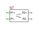
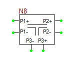
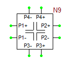
The model statement specifies the name of your RF device model, in this case, MyNewRFBJT. The symbol statement determines the device type and schematic symbol. The symbol_name can only be one of the choice given in the table below. The frequency units can be hz, khz, mhz or ghz. "s" implies the s-parameters. If the complex_data_format is left blank, the S-parameters are interpreted to have Mag/Phase format, with the magnitude on a linear scale and phase expressed in degrees. The other options for complex_data_format are "ma" for magnitude expressed in dB, or "ri" for Real/Imag format. The last part specifies the reference impedance value, which must come after letter "r". In the above example, the reference impedance is 50 Ohms.
