EM.Terrano Tutorial Lesson 8: Simulating A Communications Link With Directional Antennas
Contents
What You Will Learn
In all the previous tutorial lessons, you used EM.Terrano's standard half-wave dipole transmitters together with a grid of ideal isotropic receivers. The primary objective of those lessons was to examine the received power coverage map in a multipath environment. In this tutorial lesson, you will learn how to import the radiation pattern of more sophisticated antennas and will use realistic radiator models for the receivers. With realistic antennas on the both ends of a link, you can perform link budget analysis.
![]() Back to EM.Terrano Tutorial Gateway
Back to EM.Terrano Tutorial Gateway
![]() Download projects related to this tutorial lesson
Download projects related to this tutorial lesson
Getting Started
Open the EM.Cube application and switch to EM.Terrano. Start a new project with the following parameters:
For this tutorial lesson, you will use the same Downtown Ann Arbor scene you created in Tutorial Lesson 7. You can follow the same instructions in the section titled "Constructing the Downtown Ann Arbor Scene" of the previous lesson. Alternatively, you can download the "Ann Arbor Template" project using this link.
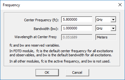
In either case, make sure to set the center frequency of the project to 5.8GHz. You can do this by clicking the Frequency ![]() button of the simulate toolbar or using the keyboard shortcut Ctrl+F to open the Frequency Dialog. The simplest way to open this dialog is to double-click on the frequency box of the Status Bar located at the bottom of the screen.
button of the simulate toolbar or using the keyboard shortcut Ctrl+F to open the Frequency Dialog. The simplest way to open this dialog is to double-click on the frequency box of the Status Bar located at the bottom of the screen.
Use the Basic Link Wizard to create a vertically polarized dipole transmitter and a grid of vertically polarized dipole receivers. Use the following parameters for the wizard:
| Parameter Name | Default Value | New Value |
|---|---|---|
| area_size | 500 | 850 |
| Tx Location X | 0 | 400 |
| Tx Location Y | 0 | 580 |
| Transmitter Height | 10 | 5 |
| Receiver Height | 1.5 | 1.5 |
| Receiver Spacing | 5 | 10 |
Change the coordinates of the point radiator "RXA" to (0, 0, rx_h) and change the Element Count along the Y direction to 0.9* rx_count.
Your Ann Arbor scene should look like the figure the below:
Using Half-Wave Co-Polarized & Cross-Polarized Dipole Receivers
Your transmitter and receivers are vertically (Z-directed) polarized half-wave dipole antenna.
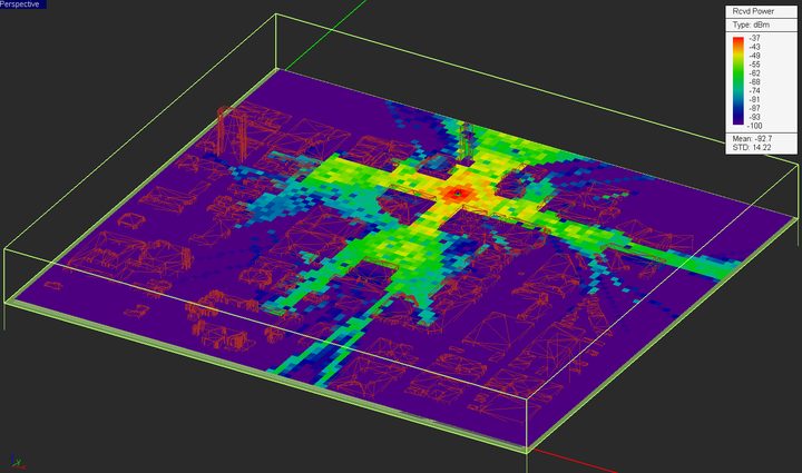
Run a quick SBR analysis at the current location of the transmitter to establish a baseline for a vertically polarized dipole transmitter and receivers. Visualize the coverage map of your propagation scene.
Next, open the property dialog of the receiver set and change the direction of the half-wave dipole radiator to "X". Run a new SBR simulation. Repeat the same procedure and change the receiver dipoles' polarization to "Y". the figures below shows the coverage maps for the two cases of X-directed and Y-directed horizontally polarized dipole receivers.
From the above two figures you can see that the maximum receiver power in the case of cross-polarized receivers drops down by 26dB with respect to the case of co-polarized receivers.
Importing External Antenna Radiation Patterns for the Transmitter & Receivers
In EM.Cube, the 3D radiation pattern of radiators is stored in an ASCII data file with a ".RAD" file extension. This file has a number of headers at the top and rows of data in the following format:
Phi_Angle(rad) Theta_Angle(rad) E_Theta_Real E_Theta_Imag E_Phi_Real E_Phi_Imag E_Total
EM.Terrano provides three ".RAD" files for the X-, Y- and Z-directed half-wave dipole radiators, which can be accessed from the "Models" folder under the "C:\Documents\EMAG" directory. These files are called:
| File Name | Radiator Type |
|---|---|
| DPL_STD.RAD | Z-directed vertically polarized half-wave dipole |
| DPL_STD_X.RAD | X-directed horizontally polarized half-wave dipole |
| DPL_STD_Y.RAD | Y-directed horizontally polarized half-wave dipole |
When you install EM.Cube for the first time, it places the above three radiation pattern files in the "Models" folder. Most of EM.Cube modules generate radiation pattern files automatically at the end of a physical simulation if a radiation pattern observable has already been defined. In this part of this tutorial lesson, you will import the radiation pattern of a linear 5-element vertical dipole array. The name of the radiation pattern file is "Dipole_Array1.RAD". You can download this file by clicking this link. This data was originally generated in EM.Libera as shown in the figures below:
After you download the radiation pattern file to your hard drive, open the property dialog of the transmitter point radiator set (TXB) and select the radio button labeled User Defined Antenna Pattern as the radiator type. Then click the Import button of the dialog. The Windows standard Open dialog opens up with the file type set to ".RAD". Browse your folders to find the downloaded pattern file. Select it and click the Open button. You will see the path of the downloaded file in the box next to the Import button.
Click the Transmitter Chain button of the transmitter set dialog to open the Transmitter Chain dialog. This dialog shows a block diagram of the transmitter circuit assumed by EM.Terrano. A voltage source with a source resistance of 50Ω is connected to a transmission line segment, with the antenna being its termination load. Enter 73Ω and 42.5Ω for the real and imaginary parts of the antenna's input impedance, i.e. in the boxes labeled Input Resistance and Input Reactance, respectively. Also, note that the directivity of the antenna is automatically set to 10.188dB. This value came from the header of the radiation pattern file. Keep all the other default values. You are going to assume that the transmitter antenna is connected to the voltage source with a transmission line segment of negligible length.
Next open the property dialog of the receiver radiator point set and select the radio button labeled User Defined Antenna Pattern as the radiator type. Then click the Import button of the dialog. The Windows standard Open dialog opens up again with the file type set to ".RAD". Go to the folder "C:\Documents\EMAG\Models". Select the file "DPL_STD.RAD" and click the Open button.
Click the Receiver Chain button of the receiver set dialog to open the Receiver Chain dialog. This dialog shows a block diagram of the receiver circuit assumed by EM.Terrano. The antenna is connected to a low-noise amplifier (LNA) via a transmission line segment. The output of the LNA is terminated in a matched 50Ω load. Simlilar to the transmitter case, enter 73Ω and 42.5Ω for the real and imaginary parts of the antenna's input impedance, i.e. in the boxes labeled Input Resistance and Input Reactance, respectively. Also, note that the directivity of the antenna is automatically set to 2.254dB, which is the typical directivity of a half-wave dipole radiator. Keep all the other default values and for now assume that the receiver antenna is connected to the LNA with a transmission line segment of negligible length.
Run a quick SBR analysis at the current location of the transmitter to establish a baseline for a vertically polarized dipole transmitter with a grid of vertically polarized dipole receivers. Visualize the coverage map of your propagation scene.
Computing the Signal-to-Noise Ratio (SNR)
In the first part of this tutorial lesson, it was assumed that EM.Terrano's standard half-wave dipole was directly connected to a 50Ω load. In this part, you will assume a real transmission line segment and a non-unity gain for the LNA. Open the property dialog of the receiver set and then open the receiver chain dialog. For the receiver, you need to define a system bandwidth in Hz. Keep the default receiver bandwidth of 100MHz. Also keep all the default temperatures of 300°K. Set the rest of the parameters according to the table below:
| Rx Chain Parameter | Original Value | New Value |
|---|---|---|
| Low-Noise Amplifier Gain | 0dB | 10dB |
| Low-Noise Amplifier Noise Figure | 0dB | 3dB |
| Transmission Line Attenuation Factor | 0dB/m | 0.1dB/m |
| Transmission Line Length | 0 | 0.5m |
| Antenna Input Resistance | 50Ω | 73Ω |
| Antenna Input Reactance | 0Ω | 42.5Ω |
Close the receiver chain dialog to return to the receiver set's property dialog.
EM.Terrano can also compute the connectivity map of your propagation scene. For this purpose, you need to define a "Minimum SNR" parameter for the receiver, which is the minimum required signal-to-noise ratio value to close the link and establish a connection between the transmitter and receiver. The "Minimum SNR" is set through Min Required SNR parameter in the receiver set dialog and it has a default value of 10dB. For this tutorial lesson, you will keep the default value.
Run an SBR analysis of your modified Ann Arbor propagation scene and visualize the received power coverage map as well as the connectivity map that has been added to the observables section of the navigation tree.
At the end of the SBR simulation, the value of SNR is computed for all the receivers. The receiver set dialog shows the values of both receiver power (in dBm) and SNR (in dB). For example, the figure below shows that the receiver power by receiver No. 6577 located at (390, 760m, 1.5m) is -45.961dBm and the SNR is 25.170dB. This receiver is located 180m away from the transmitter location.
The connectivity map is a binary color map. All the receivers whose computed SNR value is above this minimum are considered "Connected" and are shown in red (or white). The unconnected or disconnected receivers are shown in purple (or black). To plot the connectivity map in black and white colors, right-click on its name in the navigation tree and select Properties… from the contextual menu. In the output plot settings dialog, change the color map option from the default Basic to Rainbow.


