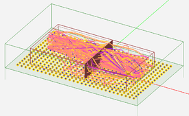
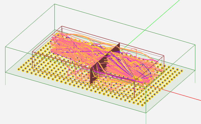
Difference between revisions of "EM.Terrano Tutorial Lesson 4 Analyzing Indoor Propagation Inside a Building Model with Penetrable Walls"
(Created page with "{{projectinfo|Tutorial| Analyzing Indoor Propagation Inside a Building Model with Penetrable Walls |PROPTUT5 19.png|In this project, you will build an indoor propagation scene...") |
|||
| Line 10: | Line 10: | ||
=== What You Will Learn === | === What You Will Learn === | ||
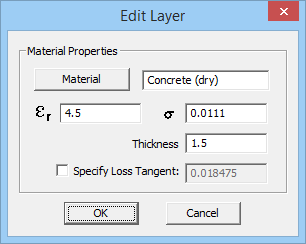
| − | In this tutorial you will set up objects with penetrable surfaces to model the walls of a building. You will change the material properties of the building walls and see their effect on the wireless propagation. | + | In this tutorial you will set up objects with penetrable surfaces to model the walls of a building. You will change the material properties of the building walls and see their effect on the wireless propagation. You will also learn how to run a discrete frequency sweep of your propagation scene. |
==Getting Started== | ==Getting Started== | ||
| Line 43: | Line 43: | ||
{{Note| Penetrable surface groups have a common wall thickness property, which has a default value of 0.5 project units. The wall thickness is implied and not visualized graphically in the CAD objects of the project workspace.}} | {{Note| Penetrable surface groups have a common wall thickness property, which has a default value of 0.5 project units. The wall thickness is implied and not visualized graphically in the CAD objects of the project workspace.}} | ||
| − | |||
| − | |||
| − | |||
| − | |||
| − | |||
| − | |||
Draw a box object with the parameters given in the table below. The top and bottom sides of a box are capped by default. Here you will uncap the bottom side so that the rays would hit the global ground. | Draw a box object with the parameters given in the table below. The top and bottom sides of a box are capped by default. Here you will uncap the bottom side so that the rays would hit the global ground. | ||
| Line 80: | Line 74: | ||
<table> | <table> | ||
<tr> | <tr> | ||
| − | <td> [[Image: | + | <td> [[Image:TER_L4_PROP1.png|thumb|500px|The property dialog of the box object.]] </td> |
</tr> | </tr> | ||
</table> | </table> | ||
| Line 140: | Line 134: | ||
<table> | <table> | ||
<tr> | <tr> | ||
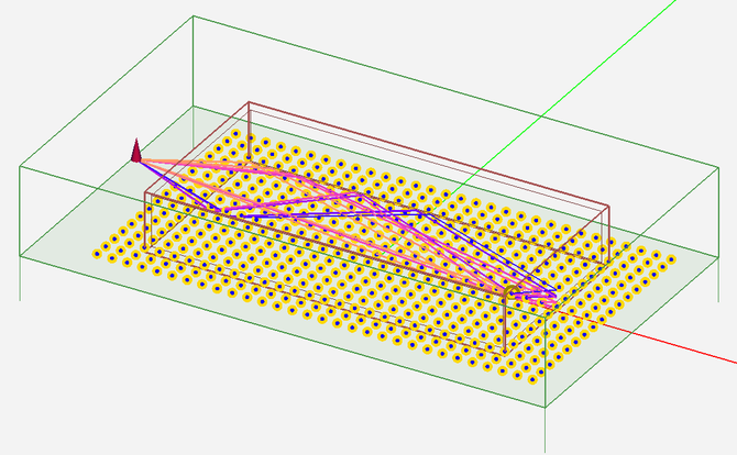
| − | <td> [[Image: | + | <td> [[Image:TER_L4_PROP2.png|thumb|570px|The propagation scene including a hollow room with brick walls.]] </td> |
</tr> | </tr> | ||
</table> | </table> | ||
| Line 152: | Line 146: | ||
<table> | <table> | ||
<tr> | <tr> | ||
| − | <td> [[Image: | + | <td> [[Image:TER_L4_PROP2b.png|thumb|670px|TEM.Terrano's simulation engine settings dialog.]] </td> |
| + | </tr> | ||
| + | </table> | ||
| + | |||
| + | <table> | ||
| + | <tr> | ||
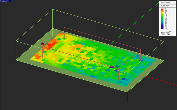
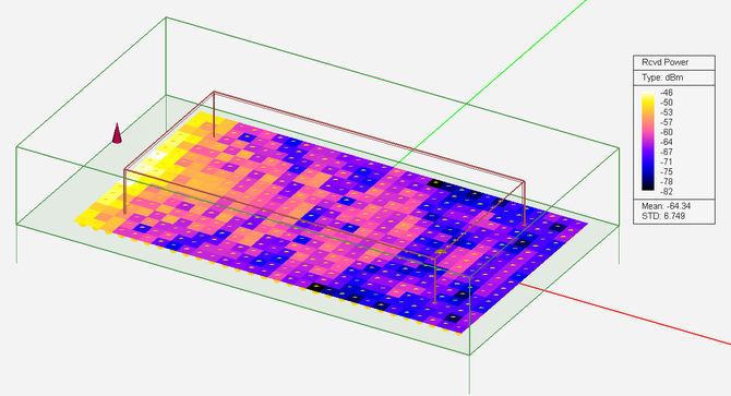
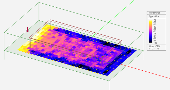
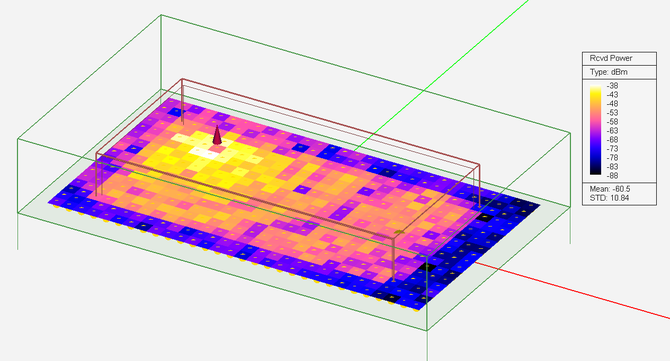
| + | <td> [[Image:TER_L4_PROP3.png|thumb|670px|The received power coverage map of the propagation scene including a hollow room with brick walls.]] </td> | ||
</tr> | </tr> | ||
</table> | </table> | ||
Revision as of 20:13, 22 July 2019
Contents
What You Will Learn
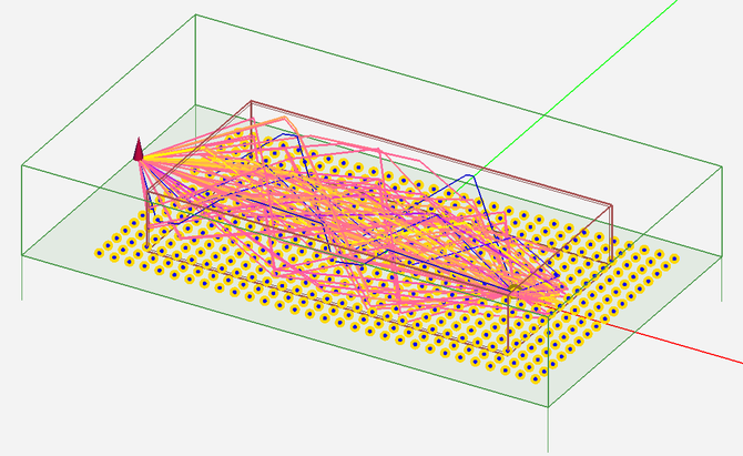
In this tutorial you will set up objects with penetrable surfaces to model the walls of a building. You will change the material properties of the building walls and see their effect on the wireless propagation. You will also learn how to run a discrete frequency sweep of your propagation scene.
Getting Started
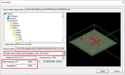
Open the EM.Cube application and switch to EM.Terrano. Start a new project with the following attributes:
Drawing a Scene with a Simple Room
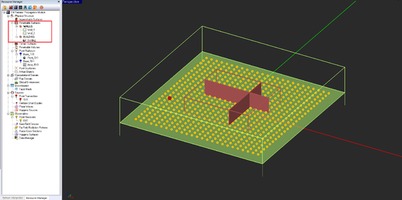
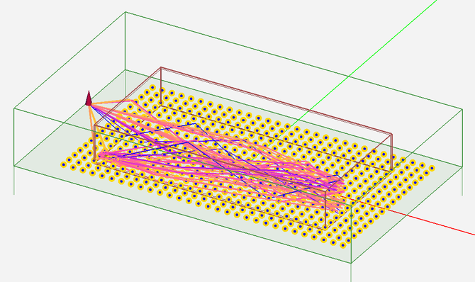
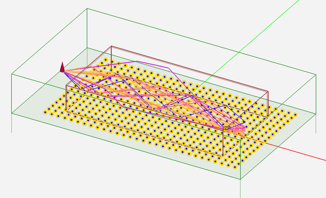
On the navigation tree, define a new penetrable surface group called Block_1 by right-clicking on the Penetrable Surfaces item in the “Physical Structure” section and selecting Insert New Block… from the contextual menu. Accept all the default settings including the “Brick” material type.
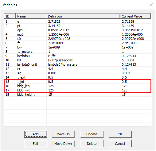
Draw a box object with the parameters given in the table below. The top and bottom sides of a box are capped by default. Here you will uncap the bottom side so that the rays would hit the global ground.
Define a vertical short dipole with the following parameters:
|
