EM.Tempo Tutorial Lesson 11: Simulating A Monopole Antenna Interacting With A Human Head Model
Contents
What You Will Learn
In this tutorial you will learn how to import several external CAD models, transfer them to EM.Tempo and combine them with your own object drawings. You will construct a physical structure with different types of materials, especially a lossy dielectric. You will use a new type of mesh generator for discretization of this structure.
![]() Back to EM.Tempo Tutorial Gateway
Back to EM.Tempo Tutorial Gateway
![]() Download projects related to this tutorial lesson
Download projects related to this tutorial lesson
Getting Started
Open the EM.Cube application and switch to EM.Tempo. Start a new project with the following attributes:
To construct the physical structure of this tutorial lesson, you need two STEP CAD models files called "Humand_Head.STP" and "Radio.STP". To download these model files click here.
Defining the Materials Groups
Create the following custom material groups in EM.Tempo:
| Group Name | Material Type | Color | Material Name | Material Properties |
|---|---|---|---|---|
| PEC_1 | PEC | Red | N/A | N/A |
| THIN_WIRE_1 | PEC | Light red | N/A | wire radius = 0.1cm |
| Dielectric_1 | Dielectric | Orange | Flesh | εr = 65, μr = 1, σ = 0.6S/m, σm = 0 |
| Dielectric_2 | Dielectric | Light green | Plastic | εr = 2.2, μr = 1, σ = 0, σm = 0 |
Note that Dielectric_1 has a very high relative permittivity and a large electric conductivity. At the center frequency of 900MHz, this is equivalent to a tangent loss of:
[math] \tan\delta = \frac{\epsilon^{\prime}}{\epsilon^{\prime\prime}} = \frac{1}{\epsilon^{\prime}}\frac{\sigma}{\omega\epsilon_0} = \frac{0.6}{(60)(2\pi \times 9\times 10^8)(8.854\times 10^{-12})} = 0.186S/m [/math]
which represents a fairly lossy dielectric material.
Importing the External Model Files
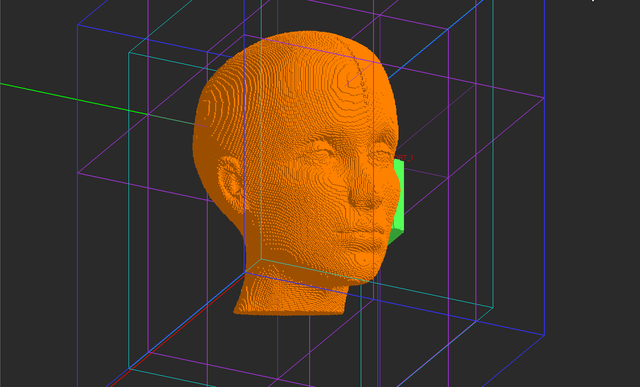
In EM.Cube, external objects are always imported to CubeCAD ![]() first. From CubeCAD you can transfer an imported object to any of the other computational modules. To import the human head model, go to File Menu and select Import.... The standard Windows Open dialog opens up with the file type set to ".STP". Browse your folders to find the downloaded CAD model file named "Human_Head.STP". Select it and click the Open button. The head model appears in the project workspace of the CubeCAD Module. Repeat the same procedure for the other CAD file named "Radio.STP" and import it to CubeCAD. A total of four solid objects are imported to CubeCAD as follows:
first. From CubeCAD you can transfer an imported object to any of the other computational modules. To import the human head model, go to File Menu and select Import.... The standard Windows Open dialog opens up with the file type set to ".STP". Browse your folders to find the downloaded CAD model file named "Human_Head.STP". Select it and click the Open button. The head model appears in the project workspace of the CubeCAD Module. Repeat the same procedure for the other CAD file named "Radio.STP" and import it to CubeCAD. A total of four solid objects are imported to CubeCAD as follows:
- Solid_1: Human Head
- Solid_2: Metal washer
- Solid_3: Metal base of antenna
- Solid_4: Plastic box
At this time, the physical structure in the project workspace should look like this:
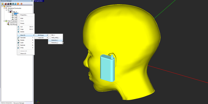
Next, you have to move all the imported solids to the various material groups in EM.Tempo. To do so, first select "Solid_1" in the navigation tree of the CubeCAD module, then right-click on it and select Move To → EM.Tempo → Dielectric_1 from the contextual menu. The human head solid will disappear from CubeCAD and will reappear in EM.Tempo's workspace under the Dielectric_1 group with an orange color.
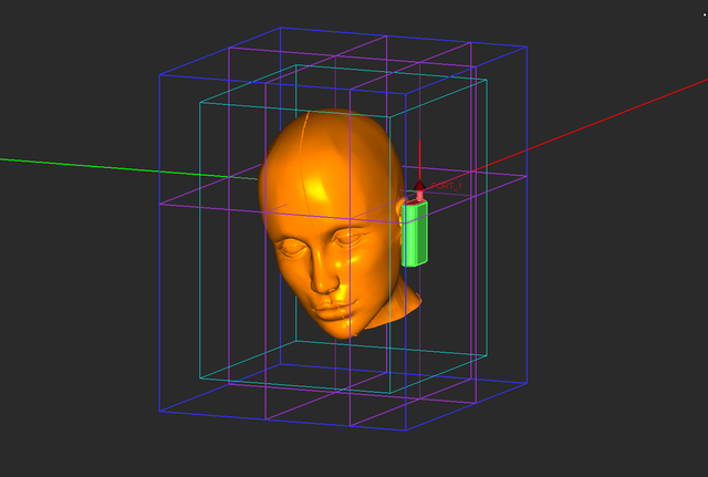
In a similar manner, move objects Solid_2 and Solid_3 from CubeCAD to the PEC_1 group in EM.Tempo and move object Solid_4 from CubeCAD to the Dielectric_2 group in EM.Tempo. At this time, the physical structure in EM.Tempo's project workspace should look like this:
Adding New Parts to Your Structure
Activate the "THIN_WIRE_1" group and draw a vertical line named "Line_1" of length 8.5cm with its LCS coordinates at (0, 0, 0) and rotation angles of (0°, -90°, -180°). With the line tool selected, click on a block space and drag the mouse to start drawing a line. While still in “Draw Mode”, press and hold down the Alt button of the keyboard. This forces the drawn line to be constrained along the alternate Z-axis (normal to the default XY plane on which the mouse pointer moves). This places your monopole antenna at the top of the imported metal base object.
Next, you will build a PEC ground plate for your monopole antenna at the top of the plastic case. You will use the "Extract Tool" for this purpose. Click on the Extract Tool ![]() button of the CAD toolbar or select the menu item Tools → Basic → Extract. Move your mouse close to the monopole and hover over the plastic casing to highlight its top face. As you can see from the figure below, you must be able to highlight the snap point at the center of the top face with rounded corners. If the mouse-over is not easy and it grabs the head model instead, you may have to freeze the object "Solid_1" first just like in the figure.
button of the CAD toolbar or select the menu item Tools → Basic → Extract. Move your mouse close to the monopole and hover over the plastic casing to highlight its top face. As you can see from the figure below, you must be able to highlight the snap point at the center of the top face with rounded corners. If the mouse-over is not easy and it grabs the head model instead, you may have to freeze the object "Solid_1" first just like in the figure.
Once the top face is highlighted, click the left mouse button to complete the primitive extraction process. A new surface object called "Surface_1" is added under the Dielectric_2" group. Move this object to the PEC_1 group in the same way you moved objects earlier from CubeCAD to EM.Tempo. This completes the geometrical construction of your physical structure for this project.
Defining the Source and Simulation Observables
Define a lumped source and place it on the Line_1 object with an offset of 0.5cm close to the metal base. The program will ask if you want to initiate a default port definition. Answer "Yes". Define a far-field radiation pattern observable with an angle increment of 3° for both Theta and Phi angles. Also, define four near-field sensor planes according to the table below:
| Field Sensor | Direction | Coordinates | Plot Type |
|---|---|---|---|
| Sensor_1 | X | (0, 0, 0) | Intensity |
| Sensor_2 | Y | (0, 0, 0) | Intensity |
| Sensor_3 | Y | (0, 15cm, 0) | Intensity |
| Sensor_4 | Z | (0, 0, 0) | Intensity |
Generating the FDTD Mesh of Your Model
So far you have used EM.Tempo's default adaptive mesh generator in all of the previous tutorial lessons. The adaptive mesh generator produces a high-fidelity discretization of your physical structure especially when it involves highly curved surfaces. But it also generates a very detailed mesh that often leads to a very large number of cells. You have to make a compromise here: practicality of the simulation (memory and computation time) vs. a less detailed mesh. Besides the adaptive FDTD mesh, EM.Tempo offers two more mesh types: regular and fixed-cell. In this tutorial lesson, you will generate a regular mesh of your physical structure.
Open EM.Tempo's mesh settings dialog and select Regular from the Mesh Type drop-down list. Set the value of Mesh Density to 15 Cells/λeff and set the value of Absolute Minimum Grid Spacing to 0.05 as a "Fraction of Max Grid Spacing in Free Space".
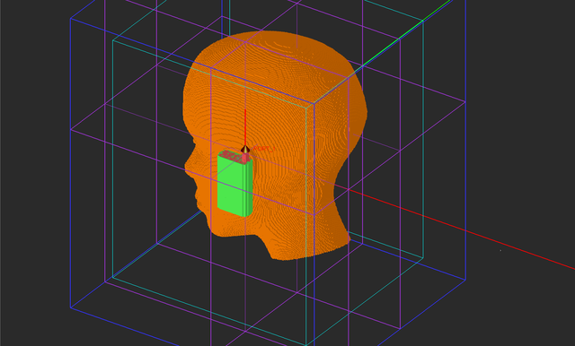
Generate and view the mesh of the human head and the radio unit. A 208 × 171 × 240 grid space is generated, which amounts to a total of more than 8.5 million cells. You have a very large computational problem at hand. Keep in mind that EM.Tempo generates the Yee mesh at the highest frequency of the bandwidth, which is 1.2GHz in this project.
| |
If your computer's RAM memory cannot handle the specified mesh settings, reduce the mesh density. |
Running an FDTD Analysis of the Combo Structure
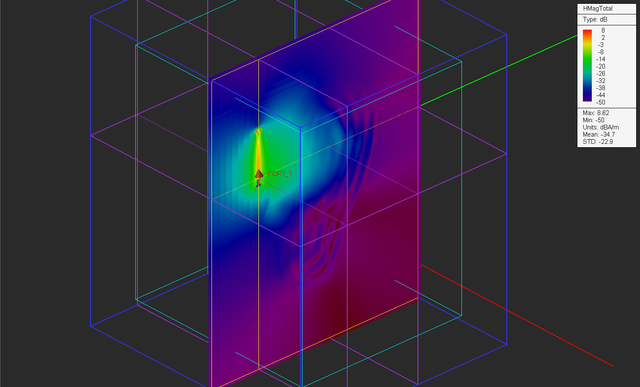
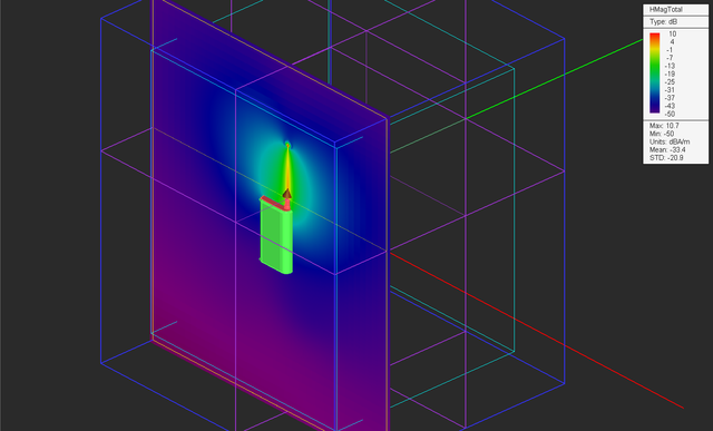
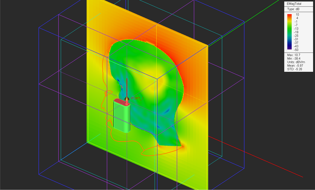
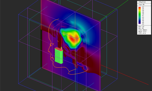
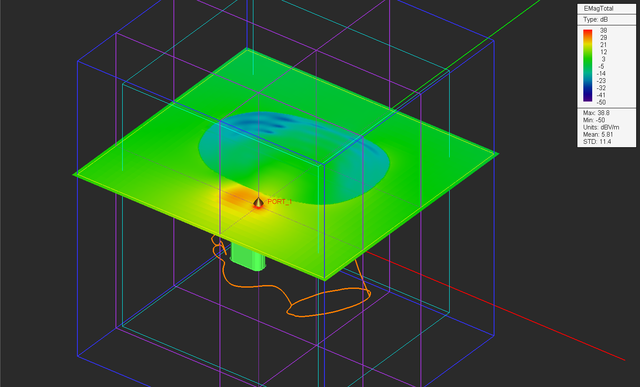
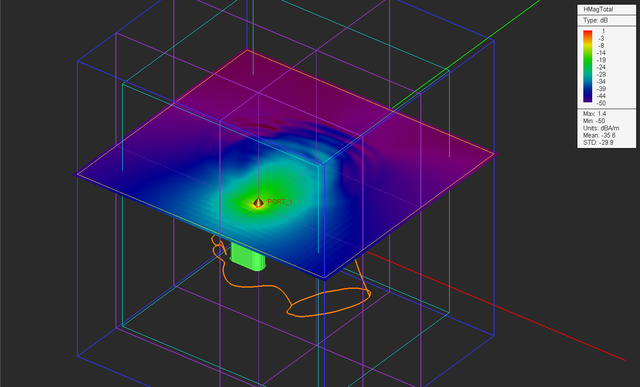
Run a wideband analysis of the combination of the human head and radio handset structure, preferably with EM.Tempo's GPU-accelerated simulation engine. If you don't have a good GPU card, use a multi-core CPU with many threads. Keep the default termination criterion. At the end of the simulation, examine the field distributions on all four sensor planes.
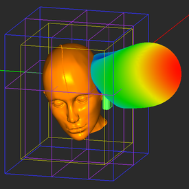
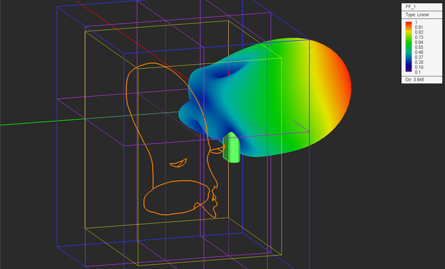
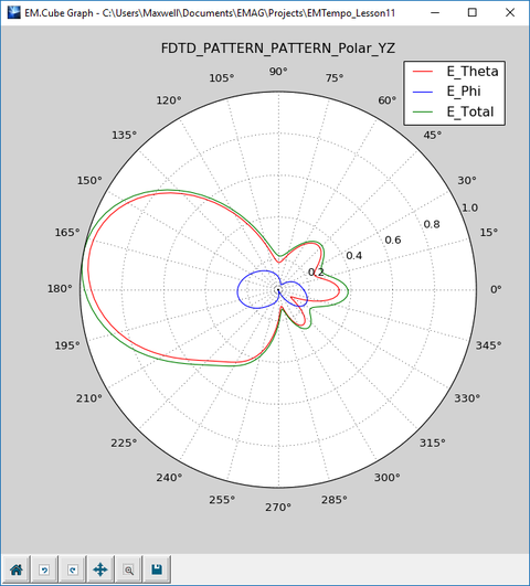
Visualize the 3D radiation pattern of the monopole antenna. See how the presence of the human head has made the radiation pattern of the monopole antenna highly directional.
Also plot the 2D polar pattern graphs. From the YZ-plane graph, you can clearly see that the radiation pattern of the monopole antenna is no longer omni-directional.
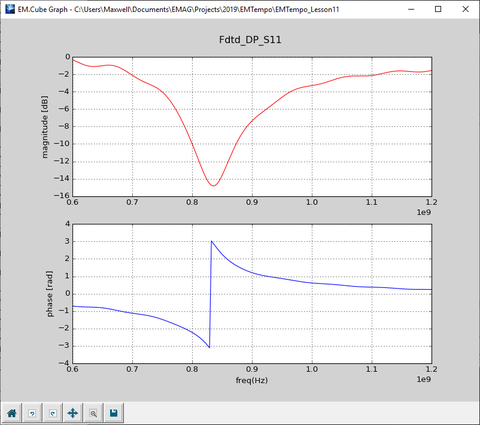
Finally, plot the S11 parameter of the antenna. You can see from the figure below the return loss is minimized around 835MHz.
