EM.Tempo Tutorial Lesson 10: Modeling Wave Propagation In Dispersive Media
Contents
- 1 What You Will Learn
- 2 Getting Started
- 3 Defining the Dielectric Material, Gaussian Beam Source & Observables
- 4 Analyzing Gaussian Beam Propagation in the Non-Dispersive Dielectric Block
- 5 Defining a Left-Handed Metamaterial
- 6 Analyzing Gaussian Beam Propagation in the Left-Handed Metamaterial Block
What You Will Learn
In this tutorial you will learn how to use Gaussian beam sources to illuminate non-dispersive and dispersive material blocks. You will also generate a fixed-cell mesh for your project and set up time-domain animation of the fields propagating inside the material blocks. In the first part of the tutorial lesson, you will consider a non-dispersive dielectric material. In the second part, you will work with a left-handed metamaterial and will explore the effect of a doubly negative refractive index on the beam propagation.
![]() Back to EM.Tempo Tutorial Gateway
Back to EM.Tempo Tutorial Gateway
![]() Download projects related to this tutorial lesson
Download projects related to this tutorial lesson
Getting Started
Open the EM.Cube application and switch to EM.Tempo. Start a new project with the following attributes:
Defining the Dielectric Material, Gaussian Beam Source & Observables
Define a dielectric material group called Dielectric_1 in the navigation tree with εr = 4, and under it, draw a dielectric box as specified below:
| Part | Object Type | Material Type | Dimensions | Coordinates | Rotation Angles |
|---|---|---|---|---|---|
| Box_1 | Box | Dielectric_1 | 80mm × 80mm × 40mm | (0, 0, -20mm) | (0°, 0°, 0°) |
Note that at the center frequency of 30GHz, the free-space wavelength is λ0 = 10mm, and your dielectric block has electrical dimensions 8λ0 × 8λ0 × 4λ0.
Next, Define a Gaussian beam source called GB_1 in the navigation tree. You will define a custom Gaussian beam box for this project. In the Gaussian Beam dialog, select the Custom radio button for the Gaussian Beam Box Type. Then, enter (-41mm, -41mm, -50mm) for the coordinates of Corner 1 and (41mm, 41mm, 50mm) for the coordinates of Corner 2 of the Gaussian Beam box. Choose the TMz polarization option and set the incident Theta and Phi angles to 165° and 0°, respectively. The Gaussian Beam source has some other parameters. Set the Radius of the Gaussian beam to 10mm. You also have to define the Focus Point, which represents the coordinate of the center of the waist of the beam. Set the focus coordinates to (0, 0, 20mm) on the top surface of the dielectric block.
EM.Tempo's field sensors, by default, display the frequency-domain field distributions computed at the sensor's specified frequency. The near-field frequency, by default, is set equal to the center frequency of your project. However, the same field sensors can be used to record the computed time-domain fields at certain time intervals. At the end of an FDTD simulation, a number of such time-domain field plots appear in the navigation tree, which you can then animate.
Define a Y-directed field sensor called Sensor_1 centered at (0, 0, 0) in the navigation tree. Define another Y-directed field sensor called Sensor_2 and centered at (0, 0, 0). But this time, in the "Sensor Domain" section, select the Time Domain radio button option, and in the "Field Display" section, select the E-Field option.
Since a large number of field plots are typically generated during an FDTD simulation, only the total E-field or total H-field will be recorded and displayed. To specify the number of plots, right-click on the Near Field Sensors item of the navigation tree and select Time Domain Settings... from the contextual menu. In the time domain settings dialog, you can specify the Sampling Interval in time steps. The default interval value is every 100 time steps. Change it to 25 time steps.
Analyzing Gaussian Beam Propagation in the Non-Dispersive Dielectric Block
EM.Tempo has three different mesh generator types. For this project, you will use the "Fixed-Cell" Mesh. Open the Mesh Settings dialog and select the Fixed-Cell option of the Mesh Type drop-down list. In the section titled "Fixed-Cell Mesh Settings", set the Cell Size to 1.2mm, 1.2mm and 0.6mm along the X, Y and Z directions, respectively.
Open the FDTD Engine Settings dialog from inside the Run dialog and set the Termination Criterion by specifying the "End Time" as 7500 time steps. Run a wideband FDTD analysis. At the end of the simulation, visualize the near field distributions on Sensor_1 plane.
| |
EM.Tempo uses a complex-valued FDTD kernel formulation in conjunction with Gaussian beam sources. As a result, the computation times are significantly longer compared to their plane wave counterparts. |
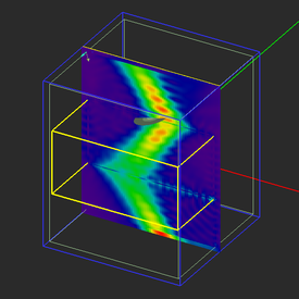
In the above figures, you can visibly see a Gaussian beam with a confined cross section area hitting the center of the top surface of the dielectric block from the left side and gets refracted inside the block. Highly dense standing wave patterns are generated inside the dielectric block. The Gaussian beam then continues to propagate into the lower half-space.
At the end of the FDTD simulation, you would notice that a large number of 3D field plots have been added under the Sensor_2 node in the navigation tree. These are the time-domain snapshots of pre-assigned total E-field distribution on this vertical sensor plane. You can animate these plots in the project workspace. Right-click on the name of the sensor in the navigation tree and select Animation from the contextual menu. The Animation Controls dialog pops up at the lower right corner of the screen. From this dialog you can modify the animation frame rate in milliseconds. The video below shows the E-field animation at various points during the FDTD time marching loop. You can clearly follow the evolution of Gaussian beam field, its collision with the top surface of the dielectric slab, its passage through the slab, the double reflection from the top and bottom surface of the dielectric slab, and the beam's exit into the lower half-space in these figures. Use the Esc key to stop the animation.
Defining a Left-Handed Metamaterial
EM.Tempo offers four types of dispersive materials:
- Debye
- Drude
- Lorentz
- Generalized Metamaterial
From the above list, the first three types are of dielectric nature and their permittivity is characterized based on their first-order or second-order pole types. A left-handed metamaterial has both permittivity and permeability tensors of uniaxial type. Each individual εrii or μrjj element can take one of the four types: Debye, Drude, Lorentz, or non-dispersive, and can have a distinct pole in general. For this project, you will set the same pole for all the six elements.
Define a Dispersive Material group of Generalized Metamaterial type called "METAMATERIAL_1" in the navigation tree. To do so, right-click on the Dispersive item in the navigation tree and select Insert New Generalized Metamaterial... from the contextual menu. In the material dialog, you have to define poles for each of the six diagonal permittivity and permeability tensor elements: εrxx, εryy, εrzz, μrxx, μryy, and μrzz. Select each permittivity or permeability component from the drop-down list labeled "Parameter" one by one. Select Drude from the Pole Type drop-down list. Keep the default value of 1 for the permittivity or permeability at infinite frequency. To define a pole, click the Add Pole button of the dialog and in the "Add Pole" dialog, enter 2.67e+11rad/s for Plasma Frequency and 1e+4rad/s for Collision Frequency. Repeat this procedure for all the six components (εrxx, εryy, εrzz, μrxx, μryy, and μrzz). Make sure all the components' Pole Types are set as Drude.
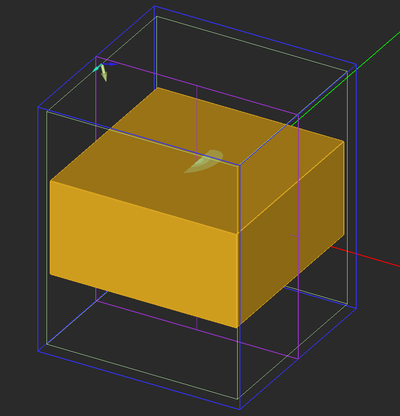
Next, move the block object Box_1 from Dielectric_1 group to METAMATERIAL_1 group. To do this, right-click on its name "Box_1" and from the contextual menu select the item Move To → EM.Tempo → METAMATERIAL_1. The Box_1 will disappear from Dielectric_1 group and will reappear under the METAMATERIAL_1 group. You will see that the color of the block changes from light green to light brown, corresponding to the dispersive material group.
Keep all the domain settings, Gaussian beam source, the two field sensors and the same coarser fixed-cell mesh settings from the last part.
| |
In this version of EM.Tempo, dispersive material objects must be finite-sized, and as such, they cannot touch the PML boundary walls. In other words, you cannot set the domain offset values equal to zero to define an unbounded dispersive medium. |
Analyzing Gaussian Beam Propagation in the Left-Handed Metamaterial Block
Keep all the domain and mesh settings and termination criterion of the previous part. Run an FDTD analysis of the left-handed metamaterial block with a TMz-polarized Gaussian beam and visualize the near-field distributions. From the figures below, you can clearly see that the wave front of the incident Gaussian beam changes direction after entering the left-handed metamaterial block and travels in the opposite direction. After the beam hits the bottom interface, it changes direction once again and continues to propagate in the lower half-space
The video below shows the E-field animation at various points during the FDTD time marching loop. Again you can easily follow the beam's change of propagation direction as it hits the dielectric metamaterial slab. Also, trace the first and second reflected beams from the top and bottom media interfaces and the exiting (transmitted) beam propagating into the lower half-space.


