EM.Illumina Tutorial Lesson 3: Computing The Radiation Pattern Of Parabolic Dish Reflectors
Contents
- 1 What You Will Learn
- 2 Getting Started
- 3 Constructing the Parabolic Dish Reflector Geometry
- 4 Examining the Object of Revolution
- 5 Defining a Short Dipole Source
- 6 Defining the Simulation Observables
- 7 Examining the Mesh of the Parabolic Dish
- 8 Running a PO Analysis of the Reflector Antenna
- 9 Examining the Radiation Characteristics of the Antenna
What You Will Learn
In this tutorial you will use a wizard to crate the geometry of a parabolic dish reflector. You will learn how to define and use a short dipole source and a far-field radiation pattern observable.
![]() Back to EM.Illumina Tutorial Gateway
Back to EM.Illumina Tutorial Gateway
![]() Download projects related to this tutorial lesson
Download projects related to this tutorial lesson
Getting Started
Open the EM.Cube application and switch to EM.Illumina. Start a new project with the following parameters:
Constructing the Parabolic Dish Reflector Geometry
Click on the Parabolic Reflector Wizard ![]() button of the Wizard Toolbar or select the menu item Tools → Component Wizards → Parabolic Reflector.
button of the Wizard Toolbar or select the menu item Tools → Component Wizards → Parabolic Reflector.
The geometry of a metallic paraboloid appears in the project workspace. This is indeed a revolution object that is generated by revolving a parabola about its primary axis. The parabolic reflector created by the wizard is fully parameterized. Open the variables dialog and change the definition of the variables "focal_len" and "axial_len" according to the table below:
| Variable Name | Original Definition | New Definition |
|---|---|---|
| focal_len | 50 | 60 |
| axial_len | 70 | 93.75 |
Examining the Object of Revolution
The object called "revolve" created by the wizard in the navigation tree is an object of revolution. Open its property dialog by right-clicking on its surface in the project works space or right-clicking on its name in the navigation tree and selecting Properties... from the contextual menu. Next, click the Primitive button in the property dialog of "revolve". It open another property dialog, which belongs to a parabola curve object that was used by the wizard to generate the object of revolution. Instead of using the wizard, you could have drawn a parabola curve first and then revolve it about its primary axis using the keyboard shortcut v. Note that the wizard set the values of the focal length and axial length parameters of the primitive parabola curve equal to the variables "focal_len" amd "axial_len", respectively. The aperture diameter of the paraboloid is shown to be 300mm.
You can also measure the aperture diameter yourself using CubeCAD's distance tool. Click the Distance Tool ![]() button of the CAD Toolbar or select the menu item Tools → Measure → Distance. Hover the mouse over the right snap point of the paraboloid object to highlight it. The color of the object turns into translucent yellow and a small dark blue ball appears at the location of the snap point. Click the left mouse to establish the first point of the distance vector. Then move the mouse in the opposite direction and hover it over the left snap point of the paraboloid object to highlight it. At this point a small dialog on the lower right corner of the screen shows a distance of 300mm.
button of the CAD Toolbar or select the menu item Tools → Measure → Distance. Hover the mouse over the right snap point of the paraboloid object to highlight it. The color of the object turns into translucent yellow and a small dark blue ball appears at the location of the snap point. Click the left mouse to establish the first point of the distance vector. Then move the mouse in the opposite direction and hover it over the left snap point of the paraboloid object to highlight it. At this point a small dialog on the lower right corner of the screen shows a distance of 300mm.
Defining a Short Dipole Source
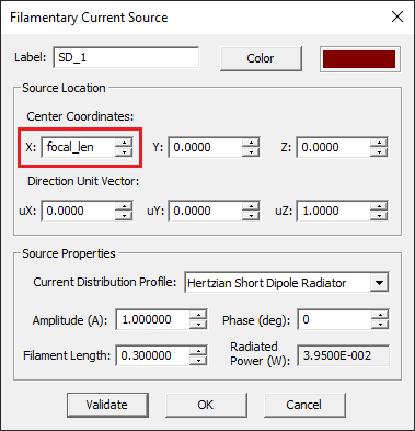
In the previous tutorial lessons you used a plane wave source to excite your physical structure. In this lesson, you will use another type of source: a short dipole radiator. This is a small Hertzian dipole antenna of infinitesimal length that has an almost omni-directional radiation pattern. In the context of Physical Optics, a short dipole radiates in all directions and illuminates the triangular cells of the physical structure's surface mesh. To define a short dipole source, right-click on the Hertzian Short Dipoles in the Sources section of the navigation tree and select Insert New Source... from the contextual menu. By default, a +Z-directed short dipole radiator is placed at the origin of coordinates (0, 0, 0). A short dipole source is indeed a filament current source. In the source dialog, you can change the coordinates of the dipole center, or its length in project units, its amplitude in Amperes and its phase in degrees. The total radiated power by the dipole source is shown in Watts. You can also specify the unit vector along the dipole by its coordinates uX, uY and uZ. The default unit vector is uX = uY = 0, uZ = 1. The length of the short dipole source is initially set to 0.001λ0. For this project, replace the numeric value of the X-coordinate of dipole source with the name of the variable "focal_len" as shown in the figure below. This places the Hertzian dipole at the focus of the paraboloid on the X-axis.
Defining the Simulation Observables
Define a default current distribution observable and three near-field sensor observables according to the table below:
| Sensor Name | Direction | Center Coordinates | Dimensions | No. Samples |
|---|---|---|---|---|
| Sensor_1 | X | (98mm, 0, 0) | (NA) × 400mm × 400mm | (NA), 200, 200 |
| Sensor_2 | Y | (50mm, 0, 0) | 150mm × (NA) × 400mm | 75, (NA), 200 |
| Sensor_3 | Z | (50mm, 0, 0) | 150mm × 400mm × (NA) | 75, 200, (NA) |
Next, define a far-field Radiation Pattern observable. To do so, right-click on the Far-Field Radiation Patterns item in the Observables section of the navigation tree and select Insert New Radiation Pattern… from the contextual menu. This opens up the Radiation Pattern dialog. Accept most of the default settings. Change the default 5° value of the Angle Increments (deg) parameter to 1° for both Theta and Phi angles. In the "Additional Radiation Characteristics" section of the dialog, check the boxes labeled Axial Ratio (AR), Half Power Beam Width (HPBW) and First Null Parameters.
The project workspace should now look like this:
Examining the Mesh of the Parabolic Dish
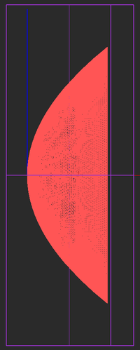
Before you run the simulation, let's first take a look at the mesh of your parabolic dish reflector. You will see a very large mesh involving thousands of triangular cells. The default mesh may seem a bit jagged due to the default 15° value of the curved edge angle tolerance parameter.
Open the mesh settings dialog first and then open the tessellation options dialog. Change the value of Curved Edge Angle Tolerance to 5°. Also, check the two boxes labeled All Single-Sided Cells and Reverse Normal.
Update the mesh using the Apply button. You should see a much smoother mesh like the figure below.
Running a PO Analysis of the Reflector Antenna
Run a PO simulation of the parabolic dish reflector and visualize the simulation results. This simulation involves a total of 19,622 cells and converges after the first IPO iteration. First, visualize the current distribution on the surface of the reflector.
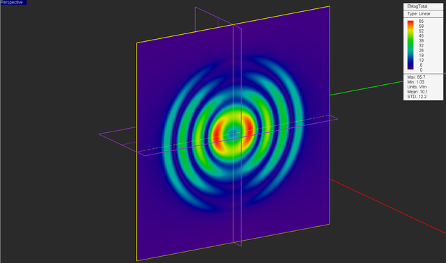
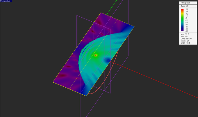
Then, visualize the electric and magnetic field distributions on the vertical plane in front of the reflector.
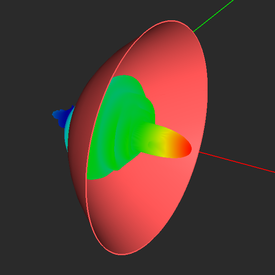
Finally, visualize the 3D radiation pattern of the parabolic dish reflector on both linear and dB scales. From the radiation pattern plot, you will see a very narrow main beam with a very high directivity of 320.1 (≅ 25.05dB).
Examining the Radiation Characteristics of the Antenna
Plot the 2D radiation patterns of the reflector antenna. Open the data manger and select the data files "FF_1_PATTERN_Cart_XY.DAT" and "FF_1_PATTERN_Cart_ZX.DAT". Open the Graph Settings dialog for each plot and change their data format to dB_Field_Scale. Then plot both graphs. From the graphs below, you can see that the side lobe levels of the radiation patterns in the two principal XY and ZX planes are less than -16dB and -22dB, respectively.
You can also view the contents of any data file in the data manager by selecting its name and clicking the View button of this dialog. The table below shows some of the computed radiation characteristics of your parabolic reflector dish antenna.
| Data File Name | Radiation Characteristic | Value |
|---|---|---|
| HPBW_XY.DAT | Half power beam width in XY palne | 5.92° |
| HPBW_ZX.DAT | Half power beam width in ZX palne | 9.47° |
| MAX_SLL_XY.DAT | Max side lobe level in XY palne | 0.1531 |
| MAX_SLL_ZX.DAT | Max side lobe level in ZX palne | 0.0611 |
| FNB_XY.DAT | First null bandwidth in XY palne | 7° |
| FNB_ZX.DAT | First null bandwidth in ZX palne | 44° |
| FNL_XY.DAT | First null level in XY palne | 0.0842 |
| FNL_ZX.DAT | First null level in ZX palne | 0.0599 |
