EM.Ferma Tutorial Lesson 3: Modeling Objects Immersed In A Uniform Electric Field
Contents
What You Will Learn
Previously, you observed that the electric field in the region between the two parallel plates of a capacitor is fairly uniform. In this tutorial you will use parallel metal plates held at different potentials to generate a uniform electric field. Then you will simulate the interaction of this uniform field with immersed objects of different material compositions.
![]() Back to EM.Ferma Tutorial Gateway
Back to EM.Ferma Tutorial Gateway
![]() Download projects related to this tutorial lesson
Download projects related to this tutorial lesson
Getting Started
Open the EM.Cube application and switch to EM.Ferma. Start a new project with the following parameters:
Creating a Uniform Electric Field
Create three Fixed-potential PEC groups in the navigation tree as follows:
| Material Group | Material Type | Color | Fixed Potential |
|---|---|---|---|
| PEC_1 | PEC | Rosy red (default) | -10V |
| PEC_2 | PEC | Orange | 10V |
| PEC_3 | PEC | Pink | 0V |
Draw the following two rectangle strip objects:
| Part | Object Type | Material Type | Dimensions | Coordinates | Rotation Angles |
|---|---|---|---|---|---|
| Rect_Strip_1 | Rectangle Strip | PEC_1 | 50mm × 50mm | (0, 0, -10mm) | (0°, 0°, 0°) |
| Rect_Strip_2 | Rectangle Strip | PEC_2 | 50mm × 50mm | (0, 0, 10mm) | (0°, 0°, 0°) |
Open the domain settings dialog and reduce the domain offset to 15mm in all the six directions. Then open the mesh settings dialog and change the fixed mesh cell size to Δx = Δy = Δz = 0.5mm. Define three field sensor observables according to the table below:
| Field Sensor | Direction | Coordinates | Plot Type | Max. Size | Cone Length Ratio | Cone Radius Ratio |
|---|---|---|---|---|---|---|
| Sensor_1 | Z | (0, 0, 0) | Intensity | - | - | - |
| Sensor_2 | X | (0, 0, 0) | Vector | 2 | 0.75 | 0.25 |
| Sensor_3 | Y | (0, 0, 0) | Intensity | - | - | - |
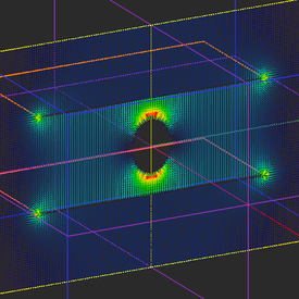
Run an electrostatic analysis of your parallel plate structure and visualize the field distributions on the three sensor planes. You can see a uniform electric field of strength |E| = (20V)/(20mm) = 1000V/m at the center plane.
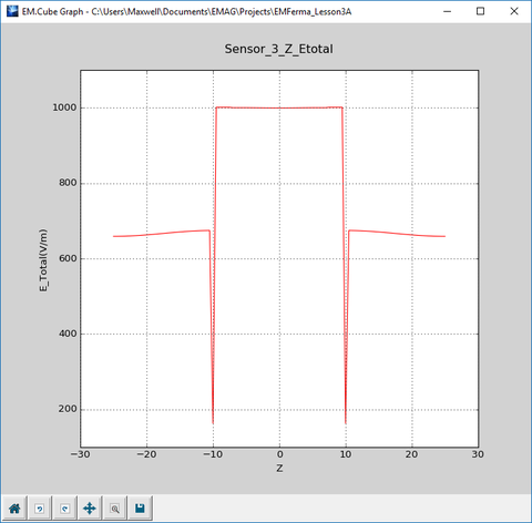
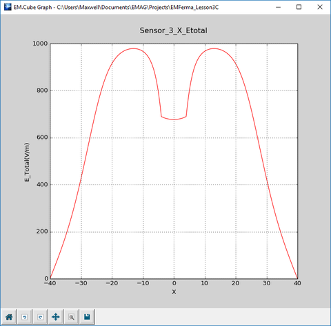
The figures below are the plots of the data files "Sensor_3_X_ETotal.DAT" and "Sensor_3_Z_ETotal.DAT". These show the variation of the electric field along the X and Z axes, respectively.
Immersing a Metallic Ellipsoid in the Uniform Field
With the PEC_3 group active in the navigation tree, draw a small ellipsoid according to the table below:
| Part Name | Object Type | Material Type | Dimensions | Coordinates | Rotation Angles |
|---|---|---|---|---|---|
| Immerse | Ellipsoid | PEC_3 | rx = 4mm, ry = 4mm, rz = 6mm | (0, 0, 0) | (0°, 0°, 0°) |
To draw a ellipsoid, click the Ellipsoid ![]() button from the Object Toolbar or select the menu item Object → Solid → Ellipsoid .
button from the Object Toolbar or select the menu item Object → Solid → Ellipsoid .
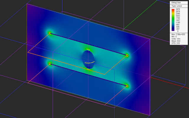
After drawing the PEC ellipsoid and placing it at the center of the gap region between the two metal plates, your physical structure should look like this:
Run an electrostatic analysis of your new structure and visualize the field distributions on the three sensor planes.
The figures below are the plots of the data files "Sensor_3_X_ETotal.DAT" and "Sensor_3_Z_ETotal.DAT". These show the variation of the electric field along the X and Z axes, respectively.
Immersing a Lossy Dielectric Ellipsoid in the Uniform Field
Define a new dielectric material group called Dielectric_1 according to the table below:
| Material Group | Material Type | εr | μr | σ | σm |
|---|---|---|---|---|---|
| Dielectric_1 | Dielectric | 4.0 | 1.0 | 100.0 | 0.0 |
Instead of deleting the PEC ellipsoid and drawing a new dielectric ellipsoid, you can simply move the object "Immerse" from the group "PEC_3" to the group "Dielectric_1". Follow the same procedure as you did in Tutorial Lesson 1 using the Move To items in the contextual menu of the spheroid object.
After drawing the PEC ellipsoid and placing it at the center of the gap region between the two metal plates, your physical structure should look like this:
Run an electrostatic analysis of your new structure and visualize the field distributions on the three sensor planes.
The figures below are the plots of the data files "Sensor_3_X_ETotal.DAT" and "Sensor_3_Z_ETotal.DAT". These show the variation of the electric field along the X and Z axes, respectively.
Analyzing the Field Discontinuities
Let's take a look at the graphs of variation of the electric field along the X-axis in the three different cases you investigated above. In the first case without any immersed object, you see a uniform electric field of 1000V/m across the region between the two metal plates, which rolls off quickly in the outside free space region. In the second case with an immersed PEC ellipsoid, there is an actual null field at the center inside the ellipsoid. In the third case with an immersed dielectric ellipsoid, there is a non-zero field of a reduced amplitude.
Now look at the variation of the electric field along the Z-axis in the third case with the dielectric spheroid. There is a sharp discontinuity at Z = ±6mm, which represent the interfaces between the air and your dielectric material. This is expected as a result of the governing boundary conditions between two different dielectric materials. The boundary conditions require that:
[math] D_{n1} = D_{n2} [/math]
or
[math] \epsilon_{r1} E_{n1} = \epsilon_{r2} E_{n2} [/math]
In the case of your dielectric material, this means that
[math] \frac{E_{z1}}{E_{z2}} = 4 [/math]
In the data manager, view the contents of the data file "Sensor_3_Z_ETotal.DAT" in the spreadsheet as shown below.
Read the field values at the points below and above the dielectric-air interface. You can see that the computed ratio agrees well with the analytical result.
[math] \frac{E_{z1}}{E_{z2}} = \frac{|E(6mm)|}{|E(5.5mm)|} = \frac{1229.00}{304.20} = 4.04 [/math]


