Difference between revisions of "User talk:Asabet"
| Line 1: | Line 1: | ||
| − | |||
====FDTD MODULE==== | ====FDTD MODULE==== | ||
| Line 45: | Line 44: | ||
CAD operations by themselves. Therefore, you can build a new project from the ground up in any of EM.Cube’s | CAD operations by themselves. Therefore, you can build a new project from the ground up in any of EM.Cube’s | ||
computational modules. | computational modules. | ||
| + | |||
| + | Before you begin to set up the geometry of your project, let’s quickly ensure that the project units are set up correctly. First, open up the Units Dialog box by selecting the Units button of the Simulate Toolbar (or using the keyboard shortcut Ctrl+U). Make sure the length units are Millimeters, and select OK to continue. Similarly, for frequency and bandwidth, select the Frequency button of the Simulate Toolbar (or use the keyboard shortcut Ctrl+F) to open the Frequency Dialog box. Make sure both the frequency and bandwidth are 1GHz, and select OK to continue. | ||
| + | |||
| + | [[Image:fdtd_lec1_2_units.png|400px]] [[Image:fdtd_lec1_4_frequency.png|400px]] | ||
| + | |||
| − | |||
[[Image:fdtd_lec1_3_newproject.png|500px]] | [[Image:fdtd_lec1_3_newproject.png|500px]] | ||
| − | + | ||
[[Image:fdtd_lec1_5_nevigation.png|500px]] | [[Image:fdtd_lec1_5_nevigation.png|500px]] | ||
[[Image:fdtd_lec1_6_toolbar.png|500px]] | [[Image:fdtd_lec1_6_toolbar.png|500px]] | ||
Revision as of 15:54, 4 June 2014
Contents
FDTD MODULE
Tutorial Lesson No. 1:
Analyzing A Center-Fed Resonant Dipole Antenna
OBJECTIVE:
To construct a center‐fed resonant dipole antenna in EM.Cube’s FDTD Module, analyze it and visualize its near and far field characteristics.
YOU WILL LEARN:
A simple half‐wave dipole antenna in free space will be analyzed in the first tutorial. This tutorial will guide you through all necessary steps required to set up and perform a basic FDTD simulation and visualize and graph the simulation results.
We strongly recommend that you read through the first few tutorials and study them carefully before setting up your own projects.
1.1 Getting Started
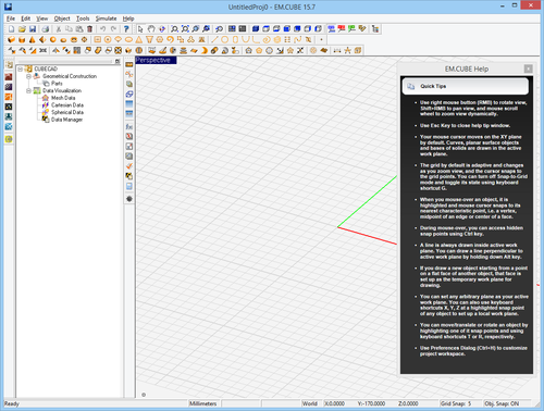
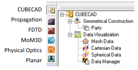
Open the EM.Cube application. Click Start, select All Programs, and then the EMAG program group. Select EM.CUBE to start the program. By default, EM.Cube opens up a blank project with the name “UntitledProj1” in its CubeCAD Module.
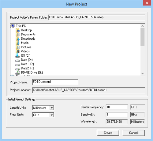
You can start drawing objects and build up your physical structure right away. Or you can initiate a new project by selecting the New button of the System Toolbar (or using the keyboard shortcut Ctrl+N, or via the menu File New Project…). This opens up the New Project Dialog, where you can enter a title for your new project and set its path. You can use the Windows Explorer to go to the desired folder where you want to place your new project folder. For this project, use the title “FDTDLesson1”. From the same dialog, you can also set the project’s Length Units, Frequency Units, Center Frequency and Bandwidth. For this tutorial lesson, set the length and frequency units of the project to Millimeters and Gigahertz, respectively, and set both the center frequency and bandwidth to 1GHz. Then, click the Create button of the dialog to accept the settings. A new project folder with your given name is immediately created at your specified path.
EM.Cube’s CubeCAD Module lets you construct 3D geometries, or import them via external model files such as *.stp, *igs, or *.stl. Once these geometries have been modified or completed, they can be moved to other modules within EM.Cube for further simulation. On the other hand, all modules of EM.Cube offer full CAD operations by themselves. Therefore, you can build a new project from the ground up in any of EM.Cube’s computational modules.
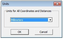
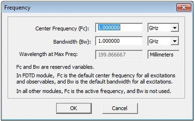
Before you begin to set up the geometry of your project, let’s quickly ensure that the project units are set up correctly. First, open up the Units Dialog box by selecting the Units button of the Simulate Toolbar (or using the keyboard shortcut Ctrl+U). Make sure the length units are Millimeters, and select OK to continue. Similarly, for frequency and bandwidth, select the Frequency button of the Simulate Toolbar (or use the keyboard shortcut Ctrl+F) to open the Frequency Dialog box. Make sure both the frequency and bandwidth are 1GHz, and select OK to continue.
