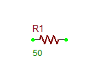
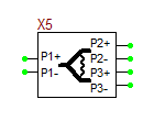
50-Ohm Load
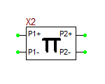
Attenuator: Pi-Type
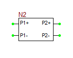
This is a four-pin, two-port device that models a resistive power attenuator with the "Pi" configuration. The characteristic impedances of the input and output transmission lines can be different. The K-parameter is the power attenuation ratio from the input to the output.
Model Identifier: attenuator Pi Bold text
Parameters:
| NAME | PARAMETER | UNITS | DEFAULT | NOTES |
|---|---|---|---|---|
| Zo1 | input line characteristic impedance | Ohms | 50.0 | |
| Zo2 | output line characteristic impedance | Ohms | 50.0 | |
| K | input/output power ratio | - | 1.0 |
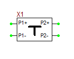
Attenuator: T-Type
This is a four-pin, two-port device that models a resistive power attenuator with the "T" configuration. The characteristic impedances of the input and output transmission lines can be different. The K-parameter is the power attenuation ratio from the input to the output.
Model Identifier: attenuator T
Parameters:
| NAME | PARAMETER | UNITS | DEFAULT | NOTES |
|---|---|---|---|---|
| Zo1 | input line characteristic impedance | Ohms | 50.0 | |
| Zo2 | output line characteristic impedance | Ohms | 50.0 | |
| K | input/output power ratio | - | 1.0 |
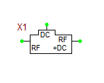
Bias Tee
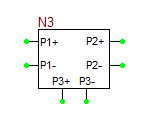
This is a six-pin, three-port device that models a passive RF bias tee. The two RF and DC inputs mix into the output (RF+DC) port.
Model Identifier: bias-tee
Parameters:
| NAME | PARAMETER | UNITS | DEFAULT | NOTES |
|---|---|---|---|---|
| L | inductance | nH | 100.0 | |
| C | capacitance | nF | 100.0 |
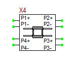
Branchline Hybrid Coupler
This is an eight-pin, four-port device that models a branchline quadrature hybrid coupler. If Port 1 acts as an input port, the output power is equally split between Ports 2 and 3. Port 2 has 90° phase shift with respect to the input, while Port 3 is in-phase with respect to the input. Port 4 acts as an isolated port. Since the branchline hybrid has a symmetric structure, any port can serve as the input port. You have to specify the center frequency of the device in GHz.
Model Identifier: branchline
Parameters:
| NAME | PARAMETER | UNITS | DEFAULT | NOTES |
|---|---|---|---|---|
| Z0 | line characteristic impedance | Ohms | 50.0 | |
| eeff | effective permittivity | - | 1.0 | |
| fc | center frequency | GHz | 1.0 | |
| len | port line segment length | mm | 10.0 |
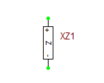
Complex Impedance
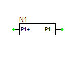
This is a two-pin, one-port device that models a generic impedance with both real and imaginary parts. It can be used in place of a one-port device when input impedance data are available rather than s11-parameter values.
Model Identifier: impedance
Parameters:
A table of z11-parameter values as a function of frequency
Generic Bend Junction
This is a four-pin, two-port device that models a bend in a general purpose transmission line. The bend geometry and the line structure can be very complicated, and their full-wave effects can be captured by the measured or simulated S-parameter data of this device. The model may also include a certain length of the transmission line at the input and output ports.
Model Identifier: bend-junction
Parameters:
A table of s11, s21, s12 and s22-parameter values as a function of frequency
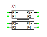
Generic Coupled T-Lines
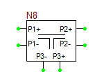
This is an eight-pin, four-port device that models a two parallel general purpose coupled transmission line segments. Ports 1 and 2 represent the input and output of the first T-Line. Ports 3 and 4 represent the input and output of the second coupled T-Line.
Model Identifier: coupled-lines
Parameters:
| NAME | PARAMETER | UNITS | DEFAULT | NOTES |
|---|---|---|---|---|
| Z0e | even mode characteristic impedance | Ohms | 50.0 | |
| Z0o | odd mode characteristic impedance | Ohms | 10.0 | |
| eeff | effective permittivity | - | 1.0 | |
| len | line segment length | mm | 10.0 |
Generic Cross Junction
This is an eight-pin, four-port device that models a cross junction among four general purpose transmission lines. The cross geometry and the line structures can be very complicated, and their full-wave effects can be captured by the measured or simulated S-parameter data of this device. The model may also include a certain length of the four transmission lines at the four ports.
Model Identifier: tee-junction
Parameters:
A table of s11, s21, s31, s41, s12, s22, s32, s42, s13, s23, s33, s43, s14, s24, s34 and s44-parameter values as a function of frequency
Generic Multiport Networks
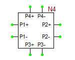
RF.Spice A/D currently offers four types of generic network devices: one-port, two-port, three-port and four-port. There are two-pin, four-pin, six-pin and eight-pin, respectively. Multiport networks can be used to model very complicated active or passive structures, which can be characterized by their measured or simulated S-parameter data.
Model Identifier: one-port, two-port, three-port, four-port
Parameters:
One-Port: A table of s11-parameter values as a function of frequency
Two-Port: A table of s11, s21, s12 and s22-parameter values as a function of frequency
Three-Port: A table of s11, s21, s31, s12, s22, s32, s13, s23 and s33-parameter values as a function of frequency
Four-Port: A table of s11, s21, s31, s41, s12, s22, s32, s42, s13, s23, s33, s43, s14, s24, s34 and s44-parameter values as a function of frequency
Generic Open End
This is a two-pin, one-port device that models the open end of a general purpose transmission line segment. Infringing capacitance effects can be captured by the measured or simulated S-parameter data of this device. The model may also include a certain length of the transmission line.
Model Identifier: open-end
Parameters:
A table of s11-parameter values as a function of frequency
Generic Open Stub
This is a two-pin, one-port device that models a general purpose transmission line segment terminated in an open end. An infinite impedance load is indeed connected to the end of the T-line segment. The fringing capacitance effects, however, are neglected by this model.
Model Identifier: stub-open
Parameters:
| NAME | PARAMETER | UNITS | DEFAULT | NOTES |
|---|---|---|---|---|
| Z0 | characteristic impedance | Ohms | 50.0 | |
| eeff | effective permittivity | - | 1.0 | |
| alpha | attenuation constant | dB/m | 0.0 | |
| len | line segment length | mm | 10.0 |
Generic Short Stub
This is a two-pin, one-port device that models a general purpose transmission line segment terminated in a shorted end. A zero impedance load is indeed connected to the end of the T-line segment. The inductive loading effects, however, are neglected by this model.
Model Identifier: stub-short
Parameters:
| NAME | PARAMETER | UNITS | DEFAULT | NOTES |
|---|---|---|---|---|
| Z0 | characteristic impedance | Ohms | 50.0 | |
| eeff | effective permittivity | - | 1.0 | |
| alpha | attenuation constant | dB/m | 0.0 | |
| len | line segment length | mm | 10.0 |
Generic Step Junction
This is a four-pin, two-port device that models a step-in-width junction between two general purpose transmission lines. The step geometry and the line structures can be very complicated, and their full-wave effects can be captured by the measured or simulated S-parameter data of this device. The model may also include a certain length of the two transmission lines at the input and output ports.
Model Identifier: step-junction
Parameters:
A table of s11, s21, s12 and s22-parameter values as a function of frequency
Generic T-Line
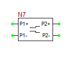
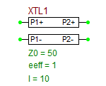
This is a four-pin, two-port device that models a general purpose transmission line segment.
Model Identifier: t-line
Parameters:
| NAME | PARAMETER | UNITS | DEFAULT | NOTES |
|---|---|---|---|---|
| Z0 | characteristic impedance | Ohms | 50.0 | |
| eeff | effective permittivity | - | 1.0 | |
| alpha | attenuation constant | dB/m | 0.0 | |
| len | line segment length | mm | 10.0 |
Generic Tee Junction
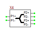
This is a six-pin, three-port device that models a tee junction among three general purpose transmission lines. The tee geometry and the line structures can be very complicated, and their full-wave effects can be captured by the measured or simulated S-parameter data of this device. The model may also include a certain length of the three transmission lines at the two through ports and the side arm.
Model Identifier: tee-junction
Parameters:
A table of s11, s21, s31, s12, s22, s32, s13, s23 and s33-parameter values as a function of frequency
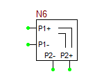
Ideal Circulator
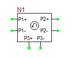
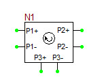
This is a six-pin, three-port device that models an ideal microwave circulator. There are two types of this device: Clockwise Circulator and Counterclockwise Circulator . The ideal circulator model is a simple non-reciprocal 3Ã3 scattering matrix fixed over all frequencies.
Model Identifier: circulator_cw & circulator_ccw
Parameters: None
Quarter-Wave Impedance Transformer
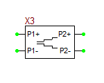
This is a four-pin, two-port device that models a quarter-wave impedance transformer. You have to specify the center frequency of the device in GHz.
Model Identifier: impedance transformer
Parameters:
| NAME | PARAMETER | UNITS | DEFAULT | NOTES |
|---|---|---|---|---|
| Zo1 | input line characteristic impedance | Ohms | 50.0 | |
| Zo2 | output line characteristic impedance | Ohms | 50.0 | |
| eeff | effective permittivity | - | 1.0 | |
| fc | center frequency | GHz | 1.0 | |
| len_in | input line segment length | mm | 10.0 | |
| len_out | output line segment length | mm | 10.0 |
Rat-Race Hybrid Coupler
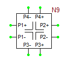
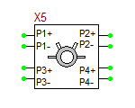
This is an eight-pin, four-port device that models a rat-race hybrid coupler. You have to specify the center frequency of the device in GHz. A rat-race coupler can be operated in a number of different modes:
- If Port 1 is used as the input port, the power will be equally split into two in-phase components at Ports 2 and 3, and Port 4 will be isolated.
- If Port 4 is used as the input port, the power will be equally split into two components with a 180° phase difference at Ports 2 and 3, and Port 1 will be isolated.
- Combiner Mode: Ports 2 and 3 act as two input ports. Then, the sum of the two inputs will form at Port 1, while their different will form at Port 4.
Model Identifier: rat-race
Parameters:
| NAME | PARAMETER | UNITS | DEFAULT | NOTES |
|---|---|---|---|---|
| Z0 | line characteristic impedance | Ohms | 50.0 | |
| eeff | effective permittivity | - | 1.0 | |
| fc | center frequency | GHz | 1.0 | |
| len | port line segment length | mm | 10.0 |
Resistive Power Divider
This is a six-pin, three-port device that models a resistive power divider with equal output powers at Ports 2 and 3. This power divider has wideband operation.
Model Identifier: resistive power divider
Parameters:
| NAME | PARAMETER | UNITS | DEFAULT | NOTES |
|---|---|---|---|---|
| Z0 | line characteristic impedance | Ohms | 50.0 | |
| eeff | effective permittivity | - | 1.0 | |
| len_in | input line segment length | mm | 10.0 | |
| len_out | output line segment length | mm | 10.0 |
Wilkinson Power Divider
This is a six-pin, three-port device that models a Wilkinson power divider with unequal output power split at Ports 2 and 3. You have to specify the center frequency of the device in GHz. It is very important to note that if the Power Ratio K is different than one, then the two output Ports 2 and 3 of the power divider must be terminated in load impedances equal to Z0 . âK and Z0 / âK, respectively.
Model Identifier: wilkinson
Parameters:
| NAME | PARAMETER | UNITS | DEFAULT | NOTES |
|---|---|---|---|---|
| Z0 | line characteristic impedance | Ohms | 50.0 | |
| eeff | effective permittivity | - | 1.0 | |
| fc | center frequency | GHz | 1.0 | |
| K | ratio of power of Port 3 to power of Port 2 | - | 1.0 | |
| len_in | input line segment length | mm | 10.0 | |
| len_out | output line segment length | mm | 10.0 |
Â
