NeoScan Manual Part F: Appendix I: Translation Stage
Appendix I: Working with Translation Stage
NeoScan Translation Stage
NeoScan translation stage is an essential part of the scanning system that allows the probe to be scanned in two directions along X or Y axis. It is composed of a two Zaber motorized Linear Translation Stages that can be controlled using the control computer and USB communications through NeoScan Mapping Utility program.
XY Linear Translation Stage
The XY Linear Translation Stage is composed of a two computer controlled motorized Linear Translation Stages that are connected in the daisy-chain via serial port (Figure A-I.1). There are two axes of motion: X and Y. The X Linear Translation Stage is mounted on the Y Linear Translation Stage. While a carriage on the X stage moves along X direction – using the rotary motors – the X stage can move along Y direction. The cables provide convenient connection of motors and encoder signals. Units with rotary motors also include a shaft-mounted knobs (Knob X and Knob Y), for manual control in the X and Y direction. The Z Linear Translation Stage (micrometer Z) on the translation stage is anticipated for precise adjustment of the probe height. A plastic probe fixtures as a supporting arm has been mounted on moving stage by a single screw, holding the probe. The probe sits inside the probe holder located on head of the probe fixture and is secured by four plastic screws.

Installing XY Linear Translation Stage
Unpack the NeoScan translation stage components. To install:
-
Place the Y Linear Translation Stage on a stable flat table, preferably an optical table. You shohld fasten it to the table by screws.
-
Mount the X Linear Translation Stage on the Y Linear Translation Stage using four screws as shown by red screws in Figure A-I.2. When the Y stage carriage is located at the start point, use the holes in the middle of the X-axis stage to attach it to the Y-axis stage carriage. The screws pass through the clearance holes in the stage base and thread into the carriage of the lower stage (Figure A-I.3). If using longer screws than the ones included, make sure that they do not go too far through the lower carriage and interfere with the stage mechanics. It may be necessary to move the carriage to gain access to the holes in the stage base.
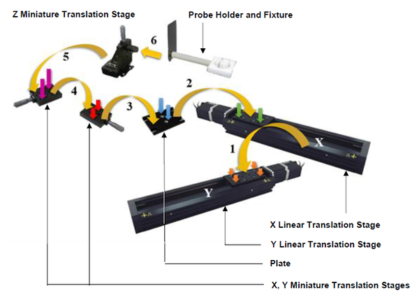 Figure A-I.2: Installing NeoScan Translation Stage.
 Figure A-I.3: Mounting the X Linear Translation Stage on the Y Linear Translation Stage using four screws.
 -
Mount the Plate on the X Linear Translation Stage. Fasten its four edges with screws as indicated by green arrows in Figure A-I.2.
-
Place X, Y, and Z Miniature Translation Stages (Micrometer) on the front edge of the Optical Plate and fasten its four edges with screws as indicated by arrows in Figure A-I.4.
 Figure A-I.4: Installing the X, Y, and Z Miniature Translation Stages (Micrometer).
 -
Attach the Plastic Probe Fixture to the Z Miniature Translation Stage.


For alignment:
-
First, loosely attach lower axis stage to breadboard using mounting bolts (Figure A-1.5).
 Figure A-I.5: Alignment. Loosely mounting the Y-axis on a flat surface (a). Aligning Y-axis (b). Aligning X-axis (c). Loosely mounting and aligning Z-axis (d).
 -
Then, use a machinist's square to align the lower axis stage with an edge of the breadboard and tighten the mounting screws.
-
Next, loosely attach the next axis and align the bases of these two stages using the machinist's square as shown. When the stages are aligned, tighten the mounting screws.
-
If a Z-axis is to be used, install it loosely as shown in Figure A-1.4. Use the machinist's square as a straight edge to align the Z-axis stage with the carriage of the stage it is attached to. It may help to have a small amount of tension on the mounting screws, so the z-axis stage can be moved, but with a little resistance. When it is aligned, tighten the screws.

A few precautions:
-
The translation stages may produce enough force to cause personal injury. Be careful to keep hair, body parts, jewelry, and clothing from being caught in moving components. Pinch labels are used on our devices to indicate areas of particular concern.
-
During continuous operation, a device’s motor may feel hot to the touch. Although this is normal, care should be taken when handling the device. If the device emits a burnt smell, it may be damaged, in which case, you should cease operation, and contact Customer Support for assistance.
-
To reduce the risk of electrostatic damage, avoid touching the electrical contacts of the data cables included with your device(s).
-
Do not expose device(s) to vibration or shock.
-
Do not expose device(s) to extreme conditions, such as temperatures exceeding device ratings, radiation, and dusty or humid environments.
-
Do not submerse device(s) in liquid.
Translation Stage Setup
-
Set up the translation stage on a stable flat table, preferably an optical table.
-
Set up the DUT near the reach of the translation stage.
-
Make sure that nothing is in the path of the translation stages.
-
Connected the X Linear Translation Stage to the USB Hub by plugging the Mini-DIN to USB serial adapter into one of the Hub’s USB ports. You may need to use a cable extension to reach the USB Hub (Figure A-I.6).
 Figure A-I.6: Daisy Chaining the Linear Translation Stages.
 -
Daisy-chain the Y Linear Translation Stage to the X Linear Translation Stage. Connect the X Linear Translation Stage mini-DIN connector to the Y Linear Translation Stage mini-DIN connector using a Male-Female extension cable.
-
A daisy-chain connection will allow both X and Y Linear Translation Stages to be controlled from a single connection to the control computer, reducing cabling demands.
-
X and Y Linear Translation Stages share power. (Note: for larger X-Y Linear Translation Stages, a power supply needs to be connected to each device in the chain).
-
-
Make sure that nothing is in the path of X and Y Linear Translation Stages. Connect the power plug of to the power connector of the X Linear Translation Stage. The green LED should light up indicating the unit has power (Figure A-I.7).
 Figure A-I.7: Translation Stage Connectors.


Grounding: To prevent damage to the device due to static buildup, the device should be properly grounded. Failure to ground the unit may result in the unit shutting down unexpectedly or ceasing to communicate with the computer. This problem can be minimized by not touching the unit during operation. If the unit fails due to static discharge, unplugging it and plugging it back in. Most Zaber devices are grounded via the shield wire of the data cables. This should normally provide a path to ground via the computer. For units which are being used without a computer, a ground lead should be connected to the chassis pin of the power supply connector.
Setting Translation Stage Parameters
Control computer can communicate to the translation stage through the USB connection for sending a command and getting a reply from it. NeoScan Mapping Utility program allows users to set the speed and the acceleration/deceleration time of the moving table and the direction of the scan. Make sure translation stage is connected to the USB Hub and then restart NeoScan Mapping Utility program.
-
Press “Hardware Settings” tab in NeoScan Mapping Utility interface (Figure A-I.8).
-
To set translation stage speed settings:
-
From “Visa COM” serial port drop-down list select the COM port that the X Linear Translation Stage is connected to. A COM port is a specific serial connection on a computer, such as COM3.
-
Set the speeds of translation stage from “Translation Speed” box (Figure A-I.8). The default value is 10 mm/s – indicating that translation stage can move 10 mm per second.
-
Press “Set Speed” button to save the new settings. The system will respond with confirmation message “Set Speed OK” in information panel.
-
The Scan Speed is ~ 0.3 mm/s.
-
When translation stages power up, they need to be homed in order to get an accurate reference position. The home sensor is at the motor end of the stage. Press “Home Position” button. Make sure that nothing is in the path of X and Y Linear Translation Stages.
-

Moving Translation Stage
To move translation stage to a defined position along the X-axis, enter the appropriate X coordinate in the X Position Setting Entry Box and then press “Move along X” button as shown in Figure A-I.9. Similarly, enter the appropriate Y coordinate in the Y Position Setting Entry Box and then press “Move along Y” button to move to the defined position.

As an example, in order to displace the translation stage to position X = +10 mm and Y = +6 mm – away from the origin (Figure A-I.10):
-
Bring both X and Y translation stages to the HOME position. This is the origin X = 0, Y = 0.
-
Enter a value of 10 (or +10) in X Position Setting Entry Box.
-
Press “Move along X” button. The X translation stages will travel to location X = 10 mm.
-
When the X translation stages reached at to location X = 10 mm, enter a value of 6 (or +6) in Y Position Setting Entry Box.
-
Press “Move along Y” button. This time the Y translation stages will move to location Y = 6 mm.

Now that the translation stage is at location X = +10 mm and Y = +6 mm (away from the origin) in order to return to the origin (X=Y=0):
-
Enter zero in X Position Setting Entry Box.
-
Press “Move along X” button. The X translation stage will travel to location X = 0 mm and Y = 6 mm.
-
Enter zero in Y Position Setting Entry Box.
-
Press “Move along Y” button. The Y translation stages will move to the origin (X=Y=0).
Alternatively, you could first enter 6 in Y Position Setting Entry Box and press “Move along Y” button and then enter 10 in X Position Setting Entry Box and press “Move along X” button.
-
“X Position” and “Y Position” in information panel indicates the current position.
Setting the Origin
The HOME position is considered to be the origin X = 0, Y = 0. In general, to set the origin
-
Enter zero in X Position Setting Entry Box in “Hardware Settings” page in NeoScan Mapping Utility program.
-
Similarly, enter zero in Y Position Setting Entry Box.
-
Press “Set Origin” button (Figure A-I.9). The system will respond with messages in information panel.
To set X = 10 mm and Y = 6 mm as the new origin, assuming both X and Y translation stages are initially at the HOME position:
-
Move the translation stage to position X = +10 mm and Y = +6 mm – away from the HOME position as discussed earlier.
-
Now the translation stage is at location X = +10 mm and Y = +6 mm:
-
Enter zero in X Position Setting Entry Box.
-
Similarly, enter zero in Y Position Setting Entry Box.
-
Press “Set Origin” button.
-
If the origin is not the HOME position, one should check that each linear translation stage travels in the correct direction (positive or negative). As shown in Figure A-I.11, the positive X is direction away from the X stepper motor and the positive Y is direction away from the Y stepper motor. For example, assume that the point X = 10 mm and Y = 6 mm is the new origin (0,0). In order to displace the translation stage to position X = -5 mm and Y = -2.5 mm – away from the origin (Figure A-I.11):
-
Enter a value of -5 in X Position Setting Entry Box.
-
Press “Move along X” button. The X translation stages will travel to location X = -5 mm.
-
When the X translation stages reached at to location X = -5 mm, enter a value of -2.5 in Y Position Setting Entry Box.
-
Press “Move along Y” button. This time the Y translation stages will move to location Y = -2.5 mm.
-
You can press “Move to Origin” button to go to the origin.

Setting the Scan Starting Point
There is no particular procedure to set the starting point of the scan. However, the following tips can be helpful for the users:
-
Setup the DUT near the translation stage and the probe (which is inside the probe holder on plastic probe fixture).
-
The probe is extremely fragile. Make sure the probe head is far away from the DUT surface and any obstacle, so you have plenty of space to maneuver The probe breaks if hit with an object.
-
Make sure the DUT is placed on a flat and level surface. Use a level for a quick measurement. Alternatively, use the micrometer mounted on top of the translation table and measure the probe height from the surface of the DUT in its three corners – as shown in Figure 4.2.
-
Move both X and Y translation stages in such a way that the probe is positioned at the center of the DUT (if possible) as shown in Figures A-I.12 and A-I.13. You can do it manually using the Knob X and Knob Y or though the NeoScan Mapping Utility program.
 Figure A-I.12: Positioning the probe at the center of the DUT when the origin is at the HOME position.
 Figure A-I.13: Positioning the probe at the center of the DUT when the origin is not at the HOME position, but at point X = 10 mm and Y = 15 mm.
 -
Use the Z Miniature Translation Stage (Micrometer) and a microscope or a powerful magnifier to adjust the desired probe height – the distance between the probe and the DUT surface. Record the micrometer reading.
- Make sure the crystal on the probe head does not hit the DUT surface. Here is a coarse estimate of how close the probe head is to the DUT surface. Illuminate the probe by the light from a desk electric lamp. Look into the microscope while lowering the probe. As the probe moves closer to the DUT, the probe shadow approaches the probe head (crystal), see Figure A-I.14.
 Figure A-I.14: A coarse estimate of how close the probe head is to the DUT surface.
 -
Raise the probe far away from the DUT surface.
-
Set the scan area (No. Points. × Step Size) and choose the scan starting point (Figure A-I.15).
 Figure A-I.15: The scan starting and end points of a patch antenna.
 -
Set the scan starting point as the origin. In order to do, move the translation stages around so that the probe is positioned at the origin and press “Set Origin” button (Figure A-1.16).
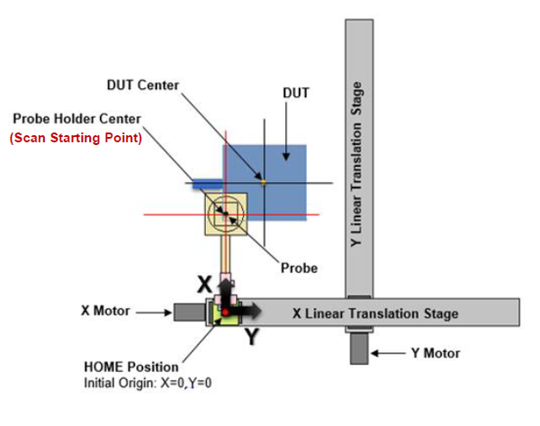 Figure A-I.16: Setting the starting point of the scan.
 -
Lower the probe to the desired height (recorded micrometer reading).


You are ready to scan. See sections 4.2.4 Scan Settings Page and 4.2.5 Scan Control Page for more details.