NeoScan Manual Part E: Real-Time Field Measurement
Contents
Capturing Fields in Real Time
Real-Time Field Measurement
In a real-time field measurement, NeoScan detects a real-time signal and display it on a high-speed digital sampling oscilloscope. Real-time measurement is used to accurately characterize broadband pulses and other waveforms. The actual pulse measurement, however, falls far below the thermal noise of the electro-optic system, and so a large number of coherent averages are required to recover it. This is accomplished by collecting successive samples on a high speed digital oscilloscope triggered by a highly stable arbitrary waveform generator which is also generating the pulse. The digital oscilloscope collects a large number of samples.
Requirements for Real-Time Measurement
The following instruments are needed for real-time measurement:
-
NeoScan Optical Mainframe
-
Either a normal or a tangential probe
-
A digital oscilloscope with averaging function and a sampling speed ≥ 4 GS/s
-
A pulse generator (RF synthesized signal generator)
-
High pass filter
-
SMA cables
-
BNC cables for 10 MHz reference
Real-Time Measurement Setup and Procedure
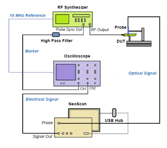
It is assumed that NeoScan Optical Bench Manager program is running and the probes has been optimized at channel 1. NeoScan Real-Time measurement setup is shown in Figure 7.1:
-
The probe stays connected to the correct fiber “Probe” of the NeoScan system.
-
Connect oscilloscope’s channel 2 to the channel of NeoScan system (“Signal Out”) with a male-to-male SMA cable.
-
Set up a RF synthesized signal generator for generating RF source to a DUT. Connect RF synthesized signal generator to DUT feed using a SMA cable.
-
Connect RF synthesized signal generator Pulse Sync Out to oscilloscope’s channel 1 via a high pass filter (such as inline filter SHP-500+). The Pulse Sync Out on the RF synthesized front panel provides the trigger in into channel 1 of the scope.
-
Synchronize the 10 MHz reference for RF synthesized signal generator and oscilloscope on their rear panels. Connect the 10 MHz OUT in the back panel of the RF synthesized signal generators to the 10 MHz IN of oscilloscope using a BNC cable.
-
Plug in the oscilloscope and RF synthesizer power cords into an electrical receptacle and turn them on.
-
Turn the RF synthesized signal generator on. Toggle the front panel RF ON/OFF key to turn on RF power to the “RF OUTPUT” port. The display “RF ON” annunciator will turn on.
-
Set the RF synthesized signal generators for pulse mode with 2 μsec period and a 120 ns pulse width.
-
Set the scope to average the output of the NeoScan channel using the math avg function – e.g. Scope resolution of 16K with maximum avg of 1000000. This eliminates the random noise.
The key here is to trigger the Pulse Sync Out of the generator. Thus, the waveform generator creates a pulse synchronously with a marker signal. The marker signal triggers the oscilloscope, and it begins sampling after a specified delay (see Figure 7.2).
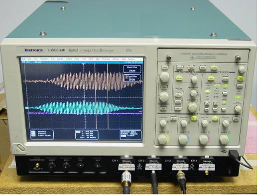
Due to the fast response of the EO crystal it is possible to measure extremely high-bandwidth signals with the normal SNR limitations of wideband signal detection. Based on this capability, NeoScan can be used as a real-time polarimetric electric field sensor system. It can be used for the measurement of wideband signals with an instantaneous bandwidth up to 20GHz. Figure 7.3 shows an example of a real time measurement of a 6.6 nsec pulse with 10 kV/m peak field strength. The upper trace shown on the oscilloscope is the received signal, and the lower trace is the detected signal.


