Glossary of EM.Cube's CAD Tools
Contents
- 1 Operational Modes of CubeCAD Tools
- 2 Generic Objects
- 3 Transform Objects
- 4 Translate Tool
- 5 Rotate Tool
- 6 Scale Tool
- 7 Link Tool
- 8 Mirror Tool
- 9 Group Tool
- 10 Array Tool
- 11 Subtract Tool
- 12 Union Tool
- 13 Intersect Tool
- 14 Creating Boolean Objects
- 15 Explode Tool
- 16 Merge Tool
- 17 Extrude Tool
- 18 Loft Tool
- 19 Revolve Tool
- 20 Fillet Tool
- 21 Skin Tool
- 22 Bridge Tool
- 23 Fill Tool
- 24 Strip-Sweep Tool
- 25 Pipe-Sweep Tool
- 26 Rail-Sweep Tool
- 27 Slice Tool
- 28 Polygonize Tool
- 29 Polymesh Tool
- 30 Consolidate Tool
- 31 Spline Tool
- 32 Roughen Tool
Operational Modes of CubeCAD Tools
Each of CubeCAD tools performs a certain operation or transformation on one or more selected CAD objects. EM.Cube provides a number of different ways to use these tools. First, you have to activate a CAD tool. Each tool has a button with a particular icon on Tools Toolbar, which you can click to activate. If you hover your mouse on one of these buttons before clicking, a small tooltip shows up displaying the name of that tool. You can also enable a tool from Tools Menu at the top of the screen. Many tools have a keyboard shortcut, which you simply type on your keyboard to enable that tool. You can also access some tools from the contextual menu of individual objects either by right-clicking on the surface of an object in the project workspace or by right-clicking on the object's name in the navigation tree. When you access a CAD tool from Tools Toolbar or Tools Menu, one or more Help Tips appear on the upper right corner of the screen, which guide you along the different steps of usage of the enabled tool.
The first step in using each CAD tool is to select one or more objects. When you activate a tool from Tools Toolbar or Tools Menu, a help tip prompts you to select an object by clicking on it. If the enabled tool allows the selection of more than one object (e.g. Group Tool), you can select the objects one by one and then press the Enter Key to finish the object selection. At this point, another help tip instructs you to take the next action. For most tools, alternatively, you can first select the object(s) and then activate the tool in one of the ways mentioned earlier. This is often more convenient and spares a few mouse clicks.
Generic Objects
EM.Cube offers a large selection of parameterized native objects. Many of CubeCAD tools, such as translate, rotate or mirror, transform native objects to other objects of the same kind or result in the creation of other types of native objects like polylines and polystrips. Some other CAD tools, result in the creation of a generic solid object, a generic surface object or a generic curve object. EM.Cube's generic objects have a limited number of parameters. They have three LCS Coordinates and three Rotation Angles, which determine their location and orientation in the project workspace. You can change these parameters by accessing the property dialog of a generic object. They also have size or dimension parameters, which are not editable. Most import operations bring in external CAD files to your project as generic objects.
Transform Objects
Many of CubeCAD operations and transformations result in the creation of either native objects like polylines and polystrips or in generic curve, surface or solid objects. Each of the following tools, however, creates a special "Transform Object":
- Group Tool
- Array Tool
- Subtract Tool
- Union Tool
- Intersect Tool
- Extrude Tool
- Loft Tool
- Revolve Tool
- Polymesh Tool
- Random Group Tool
- Roughen Tool
Each transform object has a special property dialog. The Group tool and the three Boolean operation tools, Subtract, Union and Intersect, have similar property dialogs and allow you to access their constituent objects. The property dialog of composite or Boolean objects has a Member List containing the names of all constituent objects. You can select any member and click the Edit button of the dialog to open up its property dialog, where you can edit its properties. The property dialog of all the other transform objects has an Edit Primitive button, which lets you access the property dialog of the original object used for the generation of the selected transform object.
Translate Tool
![]() Menu → Tools → Basic → Translate
Menu → Tools → Basic → Translate
KEYBOARD SHORTCUT: T
FUNCTION: Moves one or more objects to a different location by a specified translation vector
TO TRANSLATE AN OBJECT SELECTION:
- Activate the Translate Tool.
- Click on the object(s) you want to translate one by one and press the Enter Key when done.
- Next, you have to establish the translation vector. Left-click on a point in the project workspace to specify the start of the vector.
- Drag the mouse to draw a ghost of the translation vector in the desired direction. Left-click a second point to specify the end of the vector.
- The object selection is translated by the specified vector.
- A dialog pops up on the lower right corner of the screen where you can fine-tune or modify the translation vector before finalizing the translate operation.
- Using the Translate Dialog, you can also simply type in the final destination coordinates for the object selection.
PYTHON COMMAND(S):
translate_by(object,dx,dy,dz)
translate_to(object,x0,y0,z0)
Moving Objects Around Using Snap Points
The simplest and quickest way to move an object is to hover your mouse over a snap point of the object to highlight it. Then type the keyboard shortcut T. The cursor latches to the selected snap point and the Translate Dialog pops up at the lower right corner of the screen. Without clicking the mouse, begin to drag the object in the project workspace. A ghost of the object starts to move around. Click the left mouse button at the desired location to drop the object. You can fine-tune the final destination using the Translate Dialog.
Constrained Translation
When you use a snap point to translate an object, you can use the keyboard's Alt and Shift keys to constrain the object move in certain directions. The type of constraint depends on which snap point you pick to translate the object. The following rules apply:
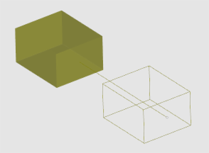
- With a face snap point selected, you can constrain translate to the direction normal to that face only by holding the Alt Key down during dragging. You can also constrain translate to the plane of that face only by holding the Shift Key down during dragging.
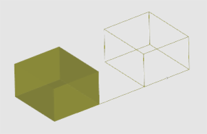
- With an edge snap point selected, you can constrain translate to the line along that edge only by holding the Shift Key down during dragging. You can also constrain translate to the line normal to that edge only by holding the Alt Key down during dragging.
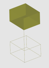
- With a vertex snap point selected, you can constrain translate to the lines along the two edges passing through that vertex only by holding the shift Key or Alt Key down during dragging.
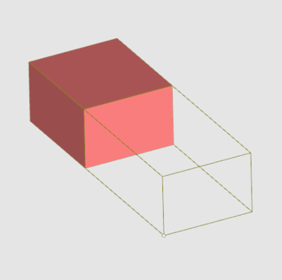
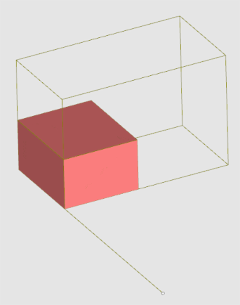
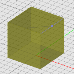
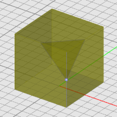
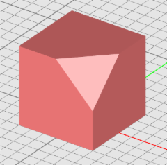
(Left) Translating a box from a face snap point while holding the Alt Key down, (Middle) Translating a box from an edge snap point while holding the shift Key down, and (Right) Translating a box from a vertex snap point while holding the shift Key down.
Rotate Tool
KEYBOARD SHORTCUT: R
FUNCTION: Rotates one or more objects about a specified axis of rotation by a specified angle
TO ROTATE AN OBJECT SELECTION:
- Activate the Rotate Tool.
- Click on the object(s) you want to translate one by one and press the Enter Key when done.
- Next, you have to establish the rotation axis. Left-click on a point in the project workspace to specify the pivot of the axis. By default, the rotation axis is oriented along the Z-axis.
- Use the keyboard's Up Arrow or Down Arrow keys to change the direction of the rotation axis or cycle through all the three X, Y, Z directions.
- Drag the mouse to establish the rotation angle. If you hold down the Shift Key while dragging the mouse, the rotation angle will increment in step of 15 degrees.
- When you reach the desired rotation angle, left-click to drop the object selection.
- A dialog pops up on the lower right corner of the screen where you can fine-tune or modify the rotation angle, the pivot coordinates or the direction of the normal vector along the rotation axis before finalizing the rotate operation.
You can align the rotation axis using the snap points of other objects in the project workspace. By default, if you click at a blank point, you establish a rotation axis normal to the current work plane. Instead, you can click at the edge snap point of another object to set the rotation axis along that edge. Or you can click on the face snap point of another object to set the rotation axis along the normal to that face. Once the rotation axis has been established, a local rotation coordinate system is created, and you can cycle through the three possible axes using the keyboard's Up Arrow or Down Arrow keys.
PYTHON COMMAND:
rotate(object,rot_angle_degree,rot_axis_x,rot_axis_y,rot_axis_z)
Rotating Objects Locally Using Snap Points
The simplest and quickest way to rotate an object locally is to hover your mouse over a snap point of an object to highlight it. Then type the keyboard shortcut R to enable the Rotate Tool. A trident depicting a local coordinate system appears at the selected snap point. You can now rotate the selected object by the desired angle. Bear in mind that each snap point has a default axis of rotation. You can cycle through the three rotational axes using the Up Arrow or Down Arrow keys. You can also constrain the angle of rotation to 15° increments by holding down the Shift Key. Left click to complete the rotation.
Rotating an object about an edge of another object.
Scale Tool
KEYBOARD SHORTCUT: S
FUNCTION: Scales the size (and generally coordinates) of one or more objects by specified scaling vectors
TO SCALE AN OBJECT SELECTION:
- Activate the Scale Tool.
- Click on the object(s) you want to scale one by one and press the Enter Key when done.
- Next, you have to establish the baseline scale vector. Left-click on a point in the project workspace to specify the start of the baseline scale vector. Then, drag the mouse to draw the vector and left-click to finish the baseline scale vector.
- Now you have to specify the final scale vector. The final scale vector has the same start point as the baseline scale vector but a different end point which determines the scale factor. As you drag the mouse, you will see the second vector drawn on top of or next to the baseline vector. Left-click one more time when you get the desired transformation.
- The scale operation performs a mapping transformation on the object selection from the baseline scale vector onto the final scale vector. As you drag the mouse to establish the end point of the final scale vector, the object selection changes both size and location as a result of the scale transformation.
- A dialog pops up on the lower right corner of the screen where you can fine-tune or modify the scale factors along the three principal axes as well the coordinates of the scale origin.
By default, objects are scaled uniformly, i.e. the scaling factors along the three principal axes are equal. From the Scale Dialog, you can change the three scaling factors arbitrarily to achieve any desired shape. Non-uniform scaling of certain objects like cylinder, cone, sphere, torus, etc., does not take effect because it would destroy the object's symmetry. On the other hand, you can enforce non-uniform scaling of objects like box, ellipsoid, ellipse strip or super-quadratic curve.
PYTHON COMMAND
scale(object,scale_factor)
Scaling Objects Locally Using Snap Points
Snap points provide an easier way of scaling objects without changing their location. Hover your mouse over a snap point of an object to highlight it and type the keyboard shortcut S. This establishes the scale origin at the selected snap point. Then, select the end point of the baseline scale vector, which can be another snap point of the same object. It is convenient to select a vertex of an object as the scale origin and select an adjacent vertex as the end point of the baseline scale vector. Next, you need to determine the final scale vector. If you drag the mouse out of the object, you will expand it. If you drag the mouse inside the object and towards the scale origin, you will shrink it.
Non-uniform scaling of a cylinder ruins its symmetry.
Constrained Scaling
While dragging the mouse to scale an object select, if you hold the Shift Key down, you can constrain the scaling to the direction along the baseline scale vector only. Alternatively, if you hold the Alt Key down, you can constrain the scaling to the direction normal to the baseline scale vector only. If the baseline vector is parallel to one of the principal axes, the "Shift Contstraint" varies only one scaling factor, while the "Alt Constraint" varies two scaling factor simultaneously.
Constrained scaling of a box along an "edge" scale vector and normal to it.
Link Tool
KEYBOARD SHORTCUT: K
FUNCTION: Links the local coordinate system (LCS) of an object to the LCS of another object
TO LINKAN AN OBJECT:
- Activate the Link Tool.
- Click on the object you want to link. A ghost of the selected object appears in the project workspace, which will float around as you drag the mouse.
- Next, hover your mouse over the second object to be linked to (the parent object) and highlight one of its snap points.
- Left-click to link the selected object. Depending on the type of the selected snap point of the second object, the orientation of the linked objects may change.
- The property dialog of the linked object opens up on the lower right corner of the screen. In the Link section of the property dialog, you will see the name of the second object as the Parent of the linked object.
The linkage relationship is one-way. The child object has a pointer to its parent and always follows it, but the opposite it not true. For example, if you move a child object, its link with its parent is broken, and it becomes an independent object.
PYTHON COMMAND
set_lcs_link(object,lcs_obj,x_off,y_off,z_off)
set_rot_link(object,lcs_obj,x_off_deg,y_off_deg,z_off_deg)
General Linking Rules
- When an object is linked, both the location and orientation of its LCS are tied to a control point of its parent object.
- The way an objects links to another object depends on the type of the parent object as well as the type of the linking control point. Objects link differently to solids, surfaces or curves.
- When an object is linked to another object's face, its local Z-axis is aligned along the normal to the plane of the parent object's face.
- When an object is linked to another object's edge, its local Y-axis is aligned along the parent object's edge, while its local X-axis is aligned along the normal to that edge. In addition, the LCS of the linked object is placed at an X-offset equal to half its X-dimension from the parent's edge. In other words, the link object is connected to the parent object from outside at the linking edge.
- When an object is linked to the nodes of a polyline or NURBS curve, the local Y-axis of the linked object is aligned with the tangent to the parent curve at the linking node.
Link Properties
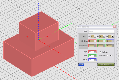
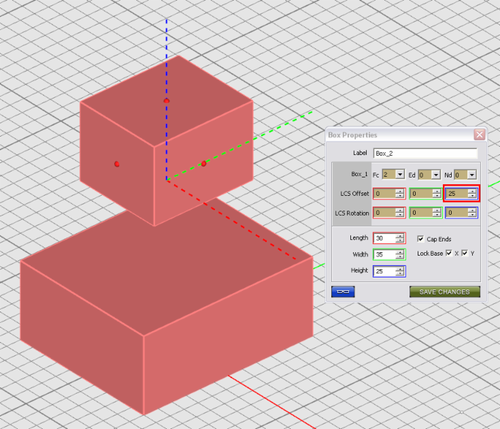
The property dialog of all objects has a Link section that contains the Parent Name and three dropdown lists labeled Fc, Ed, and Nd, standing for Face, Edge and Node, respectively. Normally, these dropdown lists are grayed out and show zero values. When an object is linked, it has to be linked to either a face, or an edge or a node (vertex) of another (patent) object. Theses primitives are ordered and indexed for each object. For example, each box has six faces. The bottom face is indexed 1, the top face is indexed 2, and so on. Each rectangular face of a box also has four edges, which are indexed from 1 to 4. The zero edge index denotes "None" or "No Edge" and corresponds to the center of that face. Each edge of a box has two nodes or vertices that are indexed as 1 or 2. In a similar fashion, the zero node index denotes "None" or "No Vertex" and corresponds to the center of that edge. In this way, the faces are indexed first, then the edges and finally the nodes or vertices. The indexing of faces, edges and nodes varies among the different object types.
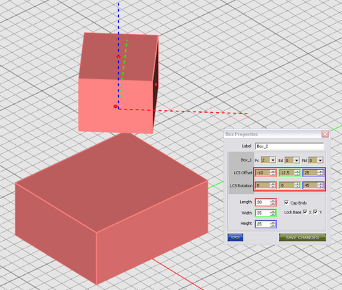
From a linked object's property dialog, you can change the link address and thus change the relative position of the linked object with respect to its parent object. Simply open one of the three Face, Edge or Node dropdown lists and change the index. The location of the link will change and the linked object is positioned on a new face, edge or vertex. EM.Cube allows offsets for linked objects. This means that the LCS of the child object can have X-, Y- and Z-offsets with respect to the parent's control point. EM.Cube also allows local rotation of linked objects. This means that the LCS of the child object can have X-, Y- and Z-rotation angles with respect to a local rotation coordinate system at the parent's control point. When an object is linked to another object, its LCS center coordinates and rotation angle values are replaced by a new set of LCS Offset and Local Rotation Angle values that are measured in a different coordinate system. We call this new coordinate system the local UVW coordinate system at the location of the parent object's control point. What you see as offsets are indeed the local U, V and W coordinates of the linked object's LCS center with respect to the parent object. Similarly, the rotation angles are measured locally at the LCS of the linked object with respect to the U, V and W axes of the parent object at the control point.
You can "Un-link" a linked object by removing its link. The simplest way to do this is to select the zero option from the Face dropdown list of the object's property dialog. Alternatively, you can also select a linked object in the project workspace and right click on its surface or right click on its name on the navigation tree and select Unlock LCS from the contextual menu to remove its link.
A box linked to the top face of another box.
A box linked to the top face of another box with a nonzero offset in the W direction.
A box linked to the top face of another box with all nonzero offsets in the U, V, W directions and rotated 45° about the local W axis.
Mirror Tool
KEYBOARD SHORTCUT: M
FUNCTION: Creates a mirror image of an object selection with respect to a specified mirror plane
TO MIRROR AN OBJECT SELECTION:
- Activate the Mirror Tool.
- Click on the object(s) you want to mirror one by one and press the Enter Key when done.
- Next, you have to establish the mirror plane. Left-click on a point in the project workspace to specify the anchor of the mirror plane. Then, drag the mouse to draw a ghost of the mirror plane.
- As you drag the mouse, the mirror plane will start to rotate around a vertical axis at the anchor point and perpendicular to the current work plane. You will also see a ghost of the image object rotating along with the mirror plane. If you hold the Shift Key down while dragging the mouse, the mirror plane rotates at increments of 15 degrees. Left-click once you get the desired mirror plane.
- A dialog pops up on the lower right corner of the screen where you can fine-tune or modify the coordinate of the anchor point and the rotation angles of the mirror plane.
You can also establish the mirror plane using the snap points of other objects in the project workspace. For example, once you select the object to be mirrored, hover your mouse on the face snap point of any object including the selected object itself, and the plane of the highlighted face will be selected as the mirror plane.
PYTHON COMMAND:
mirror(object,x0,y0,z0,uX,uY,uZ)
Mirroring Objects Locally Using Snap Points
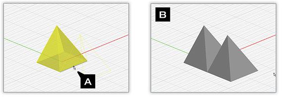
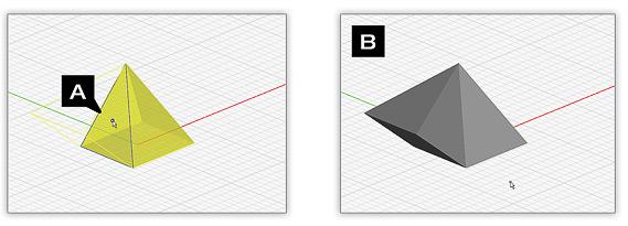
You can easily create an image of any object with respect to one of its flat faces. Hover your mouse over a face snap point of an object and type the keyboard shortcut M. The image object is formed immediately and will share the selected face with the original object.
Example 1: Defining Object Edge Mirror Planes
A. Edge snap point is defined as the mirror plane and anchor point. B. Reflected object is created along the defined construction plane.
Example 2: Defining Object Face Mirror Planes
A. Face center is defined as the mirror plane anchored point. B. Reflected object is created using the object face as a construction plane.
Example 3: Defining Arbitrary Mirror Planes
In this example, an anchor point has been selected at an arbitrary location on the grid. Once an anchor point has been defined, you can freely rotate the construction plane about the anchor point. This allows you to create a mirrored object at an arbitrary radial location.
Group Tool
KEYBOARD SHORTCUT: J
FUNCTION: Groups a selection of two or more objects into a single composite object
TO GROUP AN OBJECT SELECTION:
- Activate the Group Tool.
- The object selection is replaced with a single composite object with a new default name.
PYTHON COMMAND:
group(label,object_1,object_2,...,object_n)
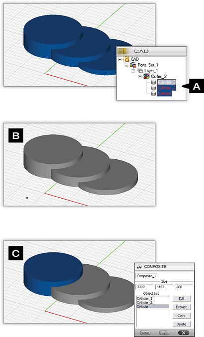
You can right-click on a composite to invoke the Composites Properties Dialog. This dialog allows you to scale the size of the composite. You can also edit or copy individual objects contained within the composite. The Extract Command removes the selected object from the group without deleting it from the scene, while the Delete command completely removes the selected object from the composite as well as the scene (C).
Array Tool
KEYBOARD SHORTCUT: A
FUNCTION: Replicates an object and forms an array of its clones based on a specified linear, rectangular or cubic grid
TO ARRAY AN OBJECT:
- Activate the Array Tool.
- Click on the object you want to array.
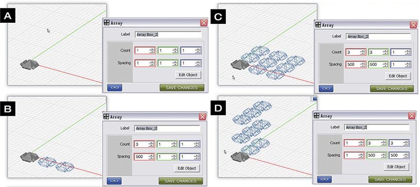
- By default, the ghost of a 2×2 array of the selected object appears in the project workspace.
- A dialog pops up on the lower right corner of the screen where you can change the number of elements and the element spacing along the three principal axes.
- Once you finalize the attributes of your new array, click the OK button of the Array Dialog to create the array object.
- The original object is replaced with a new array object with a new default name.
If your array is based on an editable object, you can modify the source object by clicking on the “Edit Object” button located in the Array Dialog. When clicked, the object’s Properties Dialog will appear. Once you have completed updating the source object, click on the close button and the array will update.
PYTHON COMMAND:
array(label,object,xCount,yCount,zCount,xSpacing,ySpacing,zSpacing)
Subtract Tool
![]() Menu → Tools → Basic → Subtract
Menu → Tools → Basic → Subtract
KEYBOARD SHORTCUT: None
FUNCTION: Subtracts one or more objects from another object in the Boolean sense
TO SUBTRACT FROM AN OBJECT:
- Activate the Subtract Tool.
- Click on the object you want to subtract from and press the Enter Key.
- Click on the object(s) you want to subtract from the previously selected object one by one and press the Enter Key when done.
- All the original selected objects are replaced with a new Boolean object with a new default name.
PYTHON COMMAND:
subtract(label,object_1,object_2)
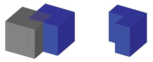
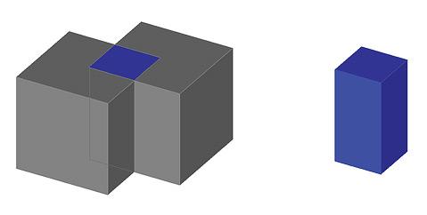
Two overlapping boxes (left) and the subtraction result (right) after subtracting the gray box from the blue one.
Union Tool
KEYBOARD SHORTCUT: U
FUNCTION: Forms a union of an object selection in the Boolean sense
TO UNION AN OBJECT SELECTION:
- Activate the Union Tool.
- Click on the objects you want to union one by one and press the Enter Key when done.
- The original object selection is replaced with a new Boolean object with a new default name.
PYTHON COMMAND:
union(label,object_1,object_2)
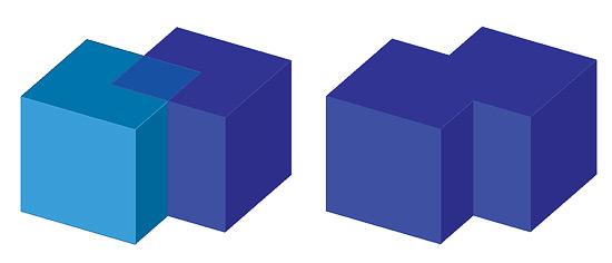
Two overlapping boxes (left) and the union result (right).
Intersect Tool
![]() Menu → Tools → Basic → Intersect
Menu → Tools → Basic → Intersect
KEYBOARD SHORTCUT: None
FUNCTION: Forms an intersection of an object selection in the Boolean sense
TO INTERSECT AN OBJECT SELECTION:
- Activate the Intersect Tool.
- Click on the objects you want to intersect one by one and press the Enter Key when done.
- The original object selection is replaced with a new Boolean object with a new default name.
PYTHON COMMAND:
intersect(label,object_1,object_2)
Two overlapping boxes (left) and the intersected result (right).
Creating Boolean Objects
Boolean operations are used to combine different object and create new ones. EM.Cube offers three Boolean operations:
- Subtraction
- Union
- Intersection
Boolean operations in EM.Cube have some limitations due to certain CAD complications. As a general rule of thumb, you can union any two or more objects of the same type. In other words, you can union two or more solids to obtain another solid. You can union two or more surface objects (planar or nonplanar) to obtain another surface objects. You can also union two curve objects under certain circumstances, although a better way to do this is to use the Merge Curve Tool Unioning two object that do not overlap each other physically is similar to grouping them into a composite object. You can subtract solids from a solid or subtract surfaces from a surface object. Similarly, your intersect solids with other or intersect surfaces with each other.
| |
Mixing solid CAD objects and surface CAD objects in Boolean operations may result in an undesirable outcome. |
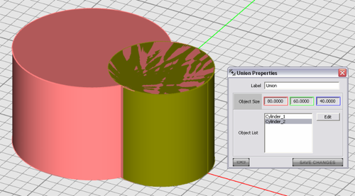
When two or more objects undergo a Boolean operation, a new Boolean object is created by default. The new Boolean object provides access to the properties of the individual constituent objects for further editing. This is a convenient feature that can effectively be used in many applications. The property dialog of Boolean objects shows the overall dimensions of the object in grayed out boxes that cannot be edited. The property dialog also has a list of all the constituent objects. These behave similar to the parent objects of linked objects. To edit the properties of a constituent, select its name in the Object List, which highlights the actual object in the Project Workspace in the current selection color. Then, click the Edit button of the dialog to open up the property dialog of the selected constituent object. At this time, EM.CUBE activates the object edit modes with red edit handles appearing on the surface of the selected constituent object. Edit the object either with the mouse using the edit handles or through the property dialog using the spin buttons and typing in new values for the object parameters. After the editing is finished, save the changes in the second property dialog and do the same for the first property dialog belonging to the Boolean object.
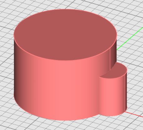
A Boolean object resulting from union of two cylinder. The cylinder on the right is selected for further editing.
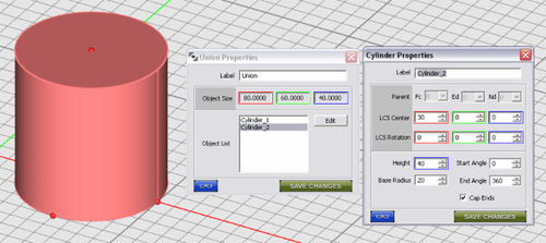
Through the property dialog of the selected cylinder, its height and radius are changed.
The Boolean object after editing one of its constituents.
Sometimes, you may prefer to get a simple solid or surface object after a Boolean operation. EM.CUBE offers the option to create generic solids or surfaces at the end of a Boolean operation. To enable this option, open the Preferences Dialog from Edit Menu or using the keyboard shortcut Ctrl+H. In the Objects tab of this dialog remove the check mark from the box labeled "Create Boolean Objects after Boolean Operations".
Explode Tool
![]() Menu → Tools → Basic → Explode
Menu → Tools → Basic → Explode
KEYBOARD SHORTCUT: Q
FUNCTION: Breaks up one or more selected objects selection into their constituent primitives
TO EXPLODE AN OBJECT SELECTION:
- Activate the Explode Tool.
- Click on the objects you want to explode one by one and press the Enter Key when done.
- The original object selection is replaced with a larger set of objects of lower dimensionality.
For example, a solid object explodes into a number of surface objects that formed its faces. A surface object explodes into a number of curve objects that formed its edges.
SPECIAL CASES OR EXCEPTIONS: Composite (group) and Boolean objects explode into their original constituent objects. An array object explodes into the set of its individual elements. A polystrip or NURBS strip object explodes into its boundary polyline or NURBS curve, respectively.
PYTHON COMMAND:
explode(object)
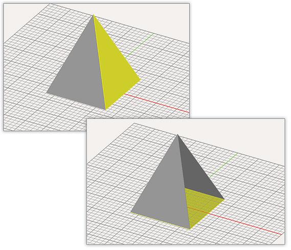
A pyramid object exploded into its constituent faces. One face has been selected and subsequently removed.
Merge Tool
KEYBOARD SHORTCUT: None
FUNCTION: Combines nodal curves (polylines or NURBS curves) into a new curve or combines polymesh objects aligned along cell edges into a new polymesh object
TO MERGE AN OBJECT SELECTION:
- Activate the Merge Tool.
- Click on the objects of the same type you want to merge one by one and press the Enter Key when done.
- The original object selection is replaced with a larger object of the same type.
If there is a gap between the objects to be merged, it is eliminated as a result of merging as the last and first nodes of the two separate curves become part of a single node list.
SPECIAL CASES OR EXCEPTIONS: In order to merge one or more polymesh objects, they have to have one or more cells strictly and exactly lined up along common edges.
PYTHON COMMAND:
merge_curve(object_1,object_2)
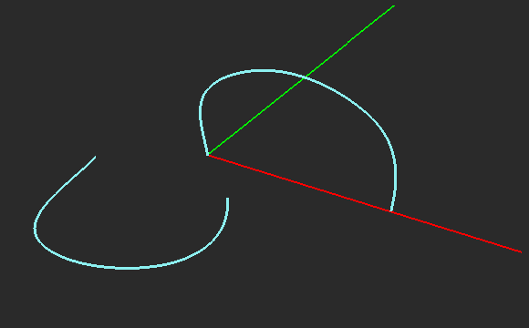
Two NURBS curve to be merged into one.
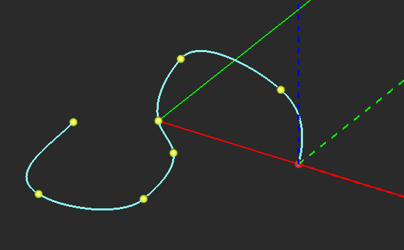
The resulting merged NURBS curve with the combine nodes.
Extrude Tool
![]() Menu → Tools → Basic → Extrude
Menu → Tools → Basic → Extrude
KEYBOARD SHORTCUT: H
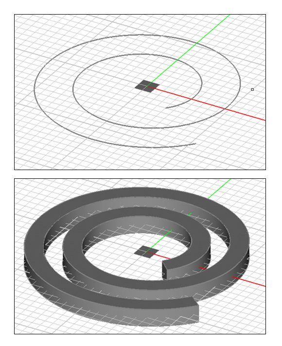
FUNCTION: Extrudes a surface object into a solid object or a curve object into a surface object
TO EXTRUDE AN OBJECT:
- Activate the Extrude Tool.
- Click on the surface or curve object you want to extrude to select it.
- Drag the mouse to lift the object and give the new dimension to it. When you reach the desired height, left-click to finalize the extrusion object.
- A dialog pops up on the lower right corner of the screen where you can fine-tune the height, change the draft angle or uncap the extrusion object.
- Make sure to click the OK button of the extrusion object's property dialog to finalize the construction.
SPECIAL CASES OR EXCEPTIONS:
PYTHON COMMAND:
extrude(label,object,extrude_height,cap_ends)
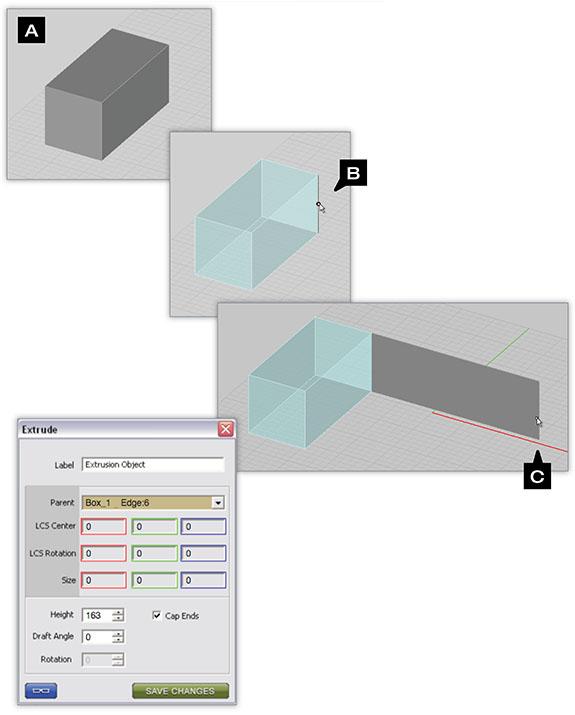
There are several extrusion options available within EM.CUBE. You can extrude the face of an object or the edge of an object. When extruding an object’s face you can also define a draft angle. When extruding the edge of an object you can define the angle of the resulting extruded plane. By default the extrusion angle is normal (perpendicular) to the plane of extrusion. You can use the snap points of nearby objects to “copy” their length, height, or width to newly extruded planes or solids
To extrude the edge Or face Of an object:
- There are two methods you can use to invoke the Extrude command:
- Method 1: Position your mouse over an unselected object’s face or edge and press the E-key on your keyboard
- Method 2: Deselect all objects in your scene, click on the Extrude Tool
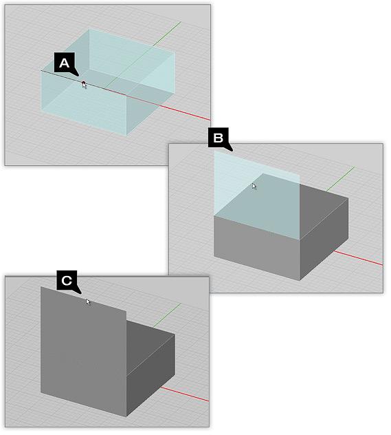
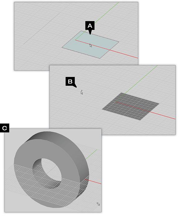
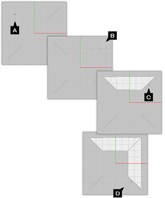
 , select the object you wish to perform an extrusion operation on and press RETURN on your keyboard. Then position you mouse cursor at the center-most point of the face or edge you wish to extrude (A).
Next, left-click on the snap point that appears and drag the extruded plane to the desired height (B).
When you have positioned the height as desired, click the left mouse button to complete the extrusion (C).
Example 1: Changing The Angle Of An Edge Extrusion
- First, follow the steps previously outlined to extrude the edge of an object (A-C below).
- Notice the Extrusion Properties Box that appears at the bottom of the Navigation Tree. You can customize the rotation angle of the plane created by the edge extrusion operation from within this box. You can also press the ARROW keys on your keyboard to quickly rotate the extruded plane’s vector 90º (D).
Example 2: Changing The Draft Angle Of An Extrusion
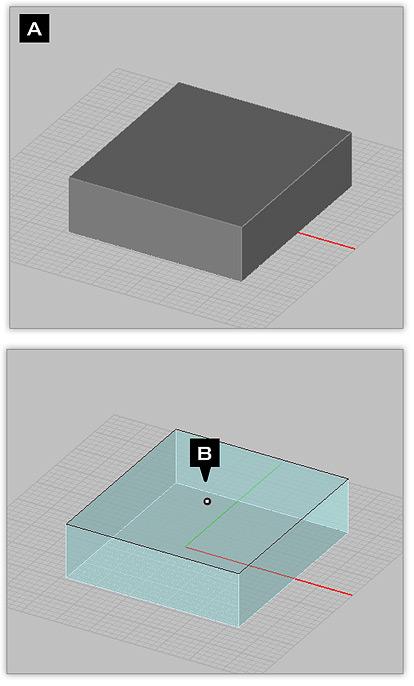
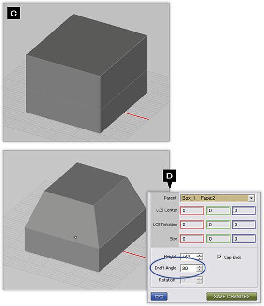
- First, follow the steps previously outlined to extrude the face of an object (A-C below).
- Once an extrusion has been created, you can change the draft angle from within the extrusion dialog box. The draft angle allows you to taper inward or flare outward the extrusion walls.
As with all property boxes, you can click on the blue preview button to preview your settings. Clicking on the green check mark will commit the current settings, while clicking on the red “x” will dismiss the dialog (D).
Loft Tool
KEYBOARD SHORTCUT: L
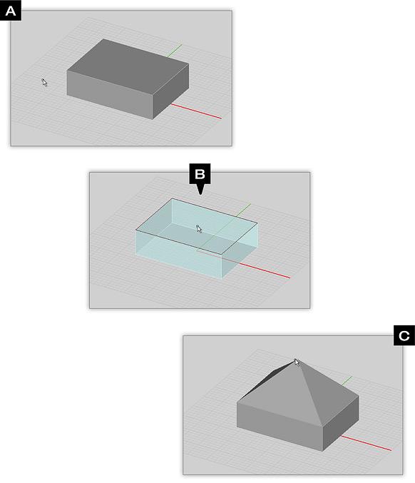
FUNCTION: Lofts a surface object to a point and turns it into a solid object or lofts a curve object to a point and turns it into a surface object
TO LOFT AN OBJECT:
- Activate the Loft Tool.
- Click on the surface or curve object you want to loft to select it.
- Drag the mouse to lift the object and give the new dimension to it. When you reach the desired height, left-click to finalize the loft object.
- A dialog pops up on the lower right corner of the screen where you can fine-tune the height and the X- and Y-offsets of the apex of the loft object.
- Make sure to click the OK button of the loft object's property dialog to finalize the construction.
SPECIAL CASES OR EXCEPTIONS:
PYTHON COMMAND:
loft(label,object,loft_height,cap_base)
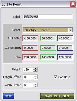
Lofted objects are linked to the objects they were generated from. This means that transformations performed on the parent object will also affect its associated loft objects. The Loft To Point properties dialog provides a number of additional parameters that can be modified.
Loft Height establishes the elevation of the loft point.
Length Offset repositions the loft point along the X axis by the specified amount. The default value is 0. Width Offset repositions the loft point along the Y axis by the specified amount. The default value is 0. Cap Base renders a plane at the base of any loft derived from the face of another object. This option is enabled by default.
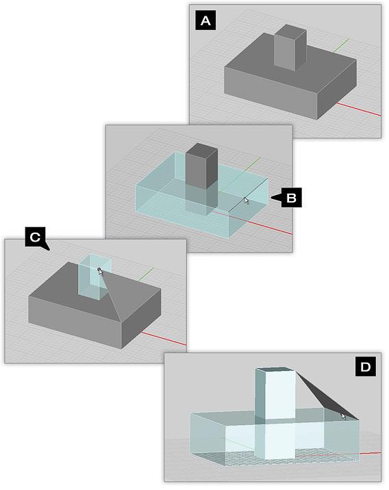
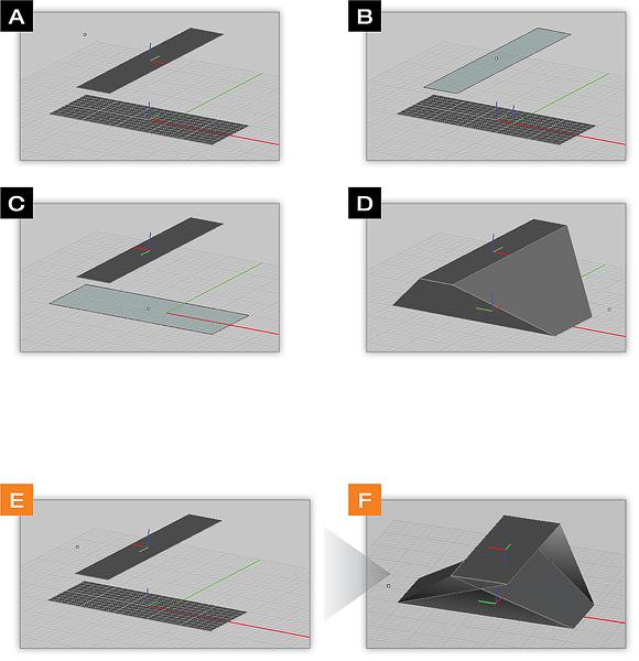
Example 1: Lofting To Snap Points
This example illustrates lofting from the edge of the lower box to a corner point on the center rectangle.
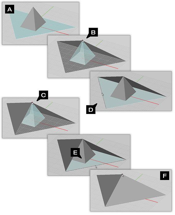
Example 2: Using Lofts To Create A Four-Sided Pyramid
Revolve Tool
![]() Menu → Tools → Basic → Revolve
Menu → Tools → Basic → Revolve
KEYBOARD SHORTCUT: V
FUNCTION: Revolves a surface or curve object about a specified axis of revolution and turns it into a solid or surface object
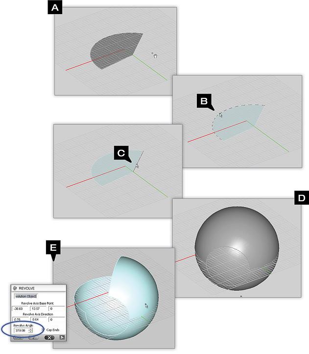
TO REVOLVE AN OBJECT:
- Activate the Revolve Tool.
- Click on the surface or curve object you want to revolve to select it.
- A trident representing a local coordinate system appears in the project workspace and floats around as you move the mouse.
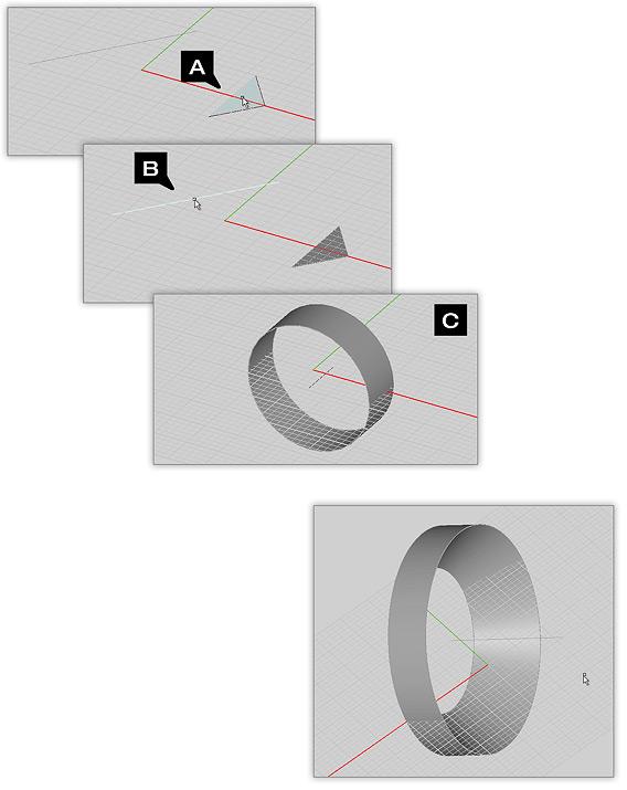
- By default, the axis of revolution is oriented perpendicular to the current work plane and is drawn larger than the other two axes. Using the keyboard's Up Arrow or Down Arrow keys, you can cycle through all the three principal directions.
- Once you get the desired axis of revolution at the right location, left-click to create the object of revolution.
- A dialog pops up on the lower right corner of the screen where you can fine-tune the coordinates of the pivot point or the direction of the axis of revolution.
- Make sure to click the OK button of the revolution object's property dialog to finalize the construction.
You can use the edges of other objects to serve as the axis of revolution. Once you select the object to be revolved, hover your mouse on the middle snap point of any straight edge of any object including the original object to be revolved, and the axis of revolution is aligned along the selected edge.
SPECIAL CASE(S):
PYTHON COMMAND:
revolve(label,object,x0,y0,z0,uX,uY,uZ,rot_angle)
In this example, a rectangular plane has been revolved by using a pre-drawn line as the axial reference.
Example 1: Revolving Polygon Planes
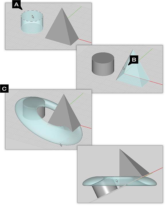
This example illustrates revolving the face of a cylinder about the axis of a pyramid"s edge.
Example 2: Complex Planar Revolutions
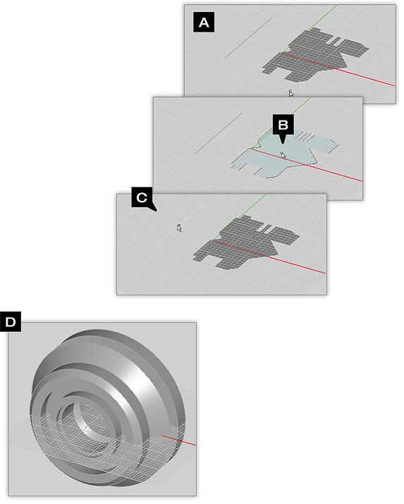
This example illustrates an extremely complex face revolved about the axis of a line.
Example 3: Unusual Revolutions
This example illustrates the face of a cylinder revolved about the axis of a pyramid"s edge.
Example 4: Partial Revolutions
This example illustrates the results of specifying a partial Rotation Angle.
Fillet Tool
KEYBOARD SHORTCUT: None
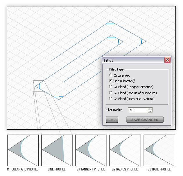
FUNCTION: Adds rounded bevels to hard-angled corners of one or more surface or curve objects
TO REVOLVE AN OBJECT:
- Activate the Fillet Tool.
- Click on the object(s) you want to fillet one by one and press the Enter Key when done.
- A dialog pops up on the lower right corner of the screen where you can change the type of fillet or fine-tune the fillet radius.
- The default option is a circular arc fillet with a radius of 10 project units. You may choose another fillet type: Linear (Chamfer), G1, G2 or G3 Blend.
- Make sure to click the OK button of the Fillet Dialog to finalize the operation.
SPECIAL CASES OR EXCEPTIONS:
PYTHON COMMAND:
fillet(object,radius)
Skin Tool
KEYBOARD SHORTCUT: None
FUNCTION: Creates a transition (skin) among two or more planar surface objects
TO SKIN PLANAR SURFACE OBJECTS:
- Activate the Skin Tool.
- Click on the planar surface object(s) you want to skin one by one and press the Enter Key when done.
- A new solid object is created in the project workspace. Note that the original surface objects are not deleted as a result of this operation.
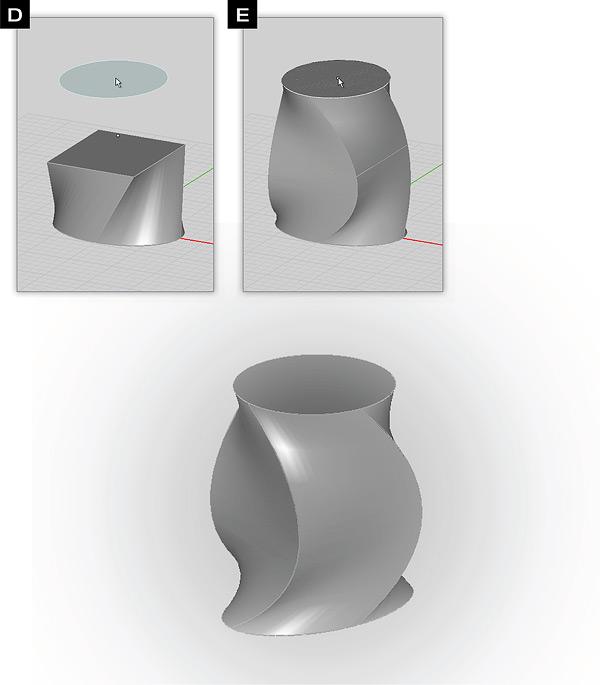
On occasion, the resulting solid object created from the skin operation may be twisted at the center. You can use the Left Arrow Key or Right Arrow Key to untwist (or twist) the transition by cycle the surface objects’ node order clockwise or counter-clockwise. You can also use the Up Arrow Key or Down Arrow Key to reverse the selected object’s node order.
SPECIAL CASES OR EXCEPTIONS:
PYTHON COMMAND:
skin(object_1,object_2,...,object_n)
NOTE how X and Y LCS coordinates of the above two planes are at right angles to each other. If the LCS orientation of each profile are not properly aligned, twisting of the skinned surface will occur. You can enable on-screen LCS (local coordinates) feedback for each object via the View menu.
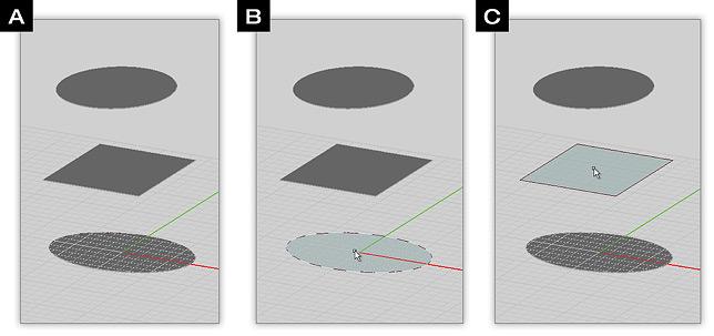
Example 1: Skinning Multiple Profiles
- Make sure all profiles are de-selected then select the Skin Tool from the CAD toolbar (A and B).
- Left click the first profile (C).
- Left click the next profile (D).
- Continue to left click on each successive profile you want to skin between.
- After clicking on the final profile, press ENTER to complete the skinning operation (E).
Bridge Tool
KEYBOARD SHORTCUT: None
FUNCTION: Creates a transition (bridge) among two or more coplanar curve objects
TO BRIDGE CURVE OBJECTS:
- Activate the Bridge Tool.
- Click on the curve object(s) you want to bridge one by one and press the Enter Key when done.
- A new surface object is created in the project workspace. Note that the original curve objects are not deleted as a result of this operation.
On occasion, the resulting surface object created from the bridge operation may be twisted at the center. You can correct this problem by pressing the Up Arrow Key to reverse the node order of the original curve objects.
SPECIAL CASES OR EXCEPTIONS:
PYTHON COMMAND:
bridge(object_1,object_2,...,object_n)
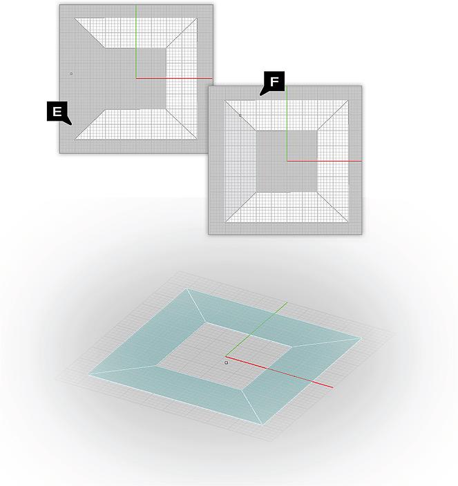
Example 1: Bridging Multiple Lines
In this example we have created a series of beveled planes by bridging between four line segments. Using this method allows you to construct planes whose edges are perfectly aligned to each other. The resulting planes can then be joined together via the Union Tool to form a solid surface.
Fill Tool
KEYBOARD SHORTCUT: None
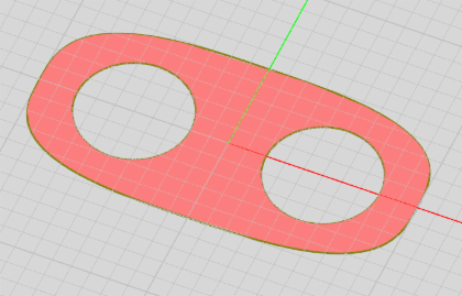
FUNCTION: Creates a planar surface object from a closed curve object or from a set of curve objects that together form a closed region
TO FILL CURVE OBJECT(S):
- Activate the Fill Tool.
- Click on the curve object(s) you want to fill one by one to select them and press the Enter Key when done.
- A new planar surface object is created in the project workspace which replaces the previously selected curve objects.
When you fill the area among several curves or lines that together form a closed region, the operation will trim any excess curve lengths.
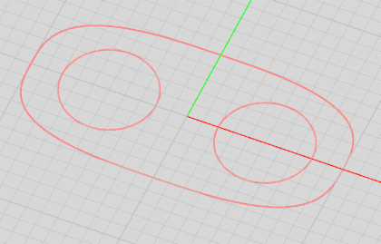
SPECIAL CASES OR EXCEPTIONS: When you fill two or more closed curves, of which one completely encloses all the others, the area among the closed curves will be filled. Filling a closed polyline or a NURBS curve results in the creation of a polystrip or a NURBS strip object, respectively.
PYTHON COMMAND:
fill_curve(object)
Three closed curves with two enclosed inside the other and the planar object resulting from filling the curves.
Strip-Sweep Tool
![]() Menu → Tools → Basic → Strip-Sweep
Menu → Tools → Basic → Strip-Sweep
KEYBOARD SHORTCUT: None
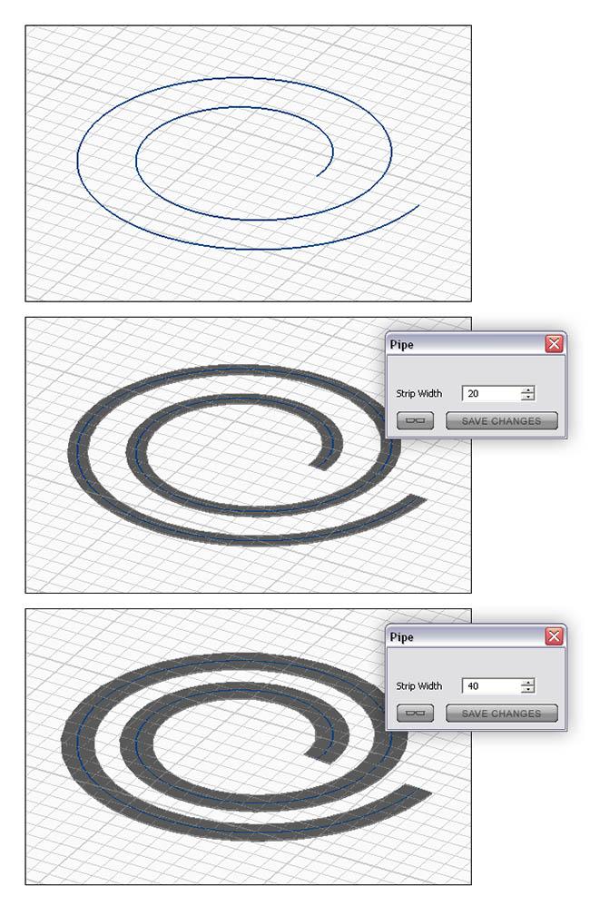
FUNCTION: Creates a flat surface object of a specified width from a curve object
TO STRIP-SWEEP CURVE OBJECT(S):
- Activate the Strip-Sweep Tool.
- Click on the curve object you want to strip-sweep.
- A dialog pops up on the lower right corner of the screen where you can modify the strip width.
SPECIAL CASES OR EXCEPTIONS: You cannot strip-sweep a polyline object because of its sharp corners. However, you can first turn the polyline into a smoother curve object using the Fillet Tool and then strip-sweep it.
PYTHON COMMAND:
strip_sweep(object,width)
Pipe-Sweep Tool
![]() Menu → Tools → Basic → Pipe-Sweep
Menu → Tools → Basic → Pipe-Sweep
KEYBOARD SHORTCUT: None
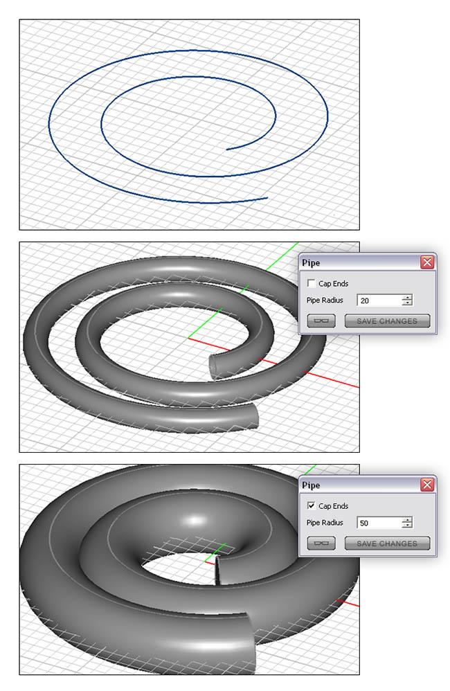
FUNCTION: Creates a tubular object of a specified radius from one or more curve objects
TO PIPE-SWEEP CURVE OBJECT(S):
- Activate the Pipe-Sweep Tool.
- Click on the curve object you want to pipe-sweep.
- A dialog pops up on the lower right corner of the screen where you can modify the pipe radius and cap the resulting surface object to turn it into a solid object.
SPECIAL CASES OR EXCEPTIONS: You cannot pipe-sweep a polyline object because of its sharp corners. However, you can first turn the polyline into a smoother curve object using the Fillet Tool and then pipe-sweep it.
PYTHON COMMAND:
pipe_sweep(object,radius)
Rail-Sweep Tool
![]() Menu → Tools → Basic → Rail-Sweep
Menu → Tools → Basic → Rail-Sweep
KEYBOARD SHORTCUT: None
FUNCTION: Sweeps a curve or planar surface object along a specified path represented by another curve object
TO RAIL-SWEEP CURVE OBJECT(S):
- Activate the Rail-Sweep Tool.
- Click on the curve object you want to rail to select it. This establishes the sweep path.
- Next, click on a surface or curve object you want to sweep along the previously specified rail path.
- A ghost of a new three-dimensional object appears in the project workspace. You can use Up Arrow or Down Arrow keys to rotate the cross section of the new object.
- Make sure to click the Enter Key to finalize the construction.
The LCS of the surface or curve object you want to sweep must positioned at the origin of coordinates on the default XY work plane. This profile will then be projected and swept along the rail path perpendicular to its curve. If the LCS of the surface or curve profile resides at a location other than the origin, you can use the Left Arrow and Right Arrow keys to slide the swept profile closer or further away from the origin. Sliding the profile changes the projection angle relative to the parent curve, which might change the shape of the resulting swept object.
SPECIAL CASES OR EXCEPTIONS: You cannot rail a polyline object because of its sharp corners. However, you can first turn the polyline into a smoother curve object using the Fillet Tool and then rail it.
PYTHON COMMAND:
rail_sweep(object_1,object_2)
Slice Tool
KEYBOARD SHORTCUT: None
FUNCTION: Splits one or more selected objects into two parts along a specified slice plane
TO SLICE AN OBJECT SELECTION:
- Activate the Slice Tool.
- Click on the object(s) you want to slice one by one and press the Enter Key when done.
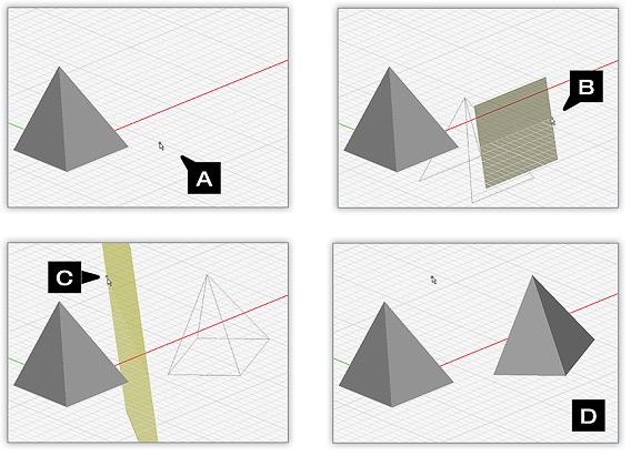
- Next, you have to establish the slice plane. Left-click on a point in the project workspace to specify the first anchor of the slice plane. By default, the slice plane is perpendicular to the current work plane.
- As you drag the mouse around, a ghost of the slice plane will appear rotating about the anchor point. Left-click a second point in the project workspace to fix the slice plane.
- The original selected objects are not replaced with sliced objects.
As a result of the slice operation, solids are sliced into smaller generic solid objects, surfaces are sliced into smaller generic surface objects and curves are sliced into smaller generic curve objects.
SPECIAL CASES OR EXCEPTIONS: You can define the slice plane alternatively using three snap points of the object to be sliced. Once the Slice Tool is enabled, click on three snap points of the selected object one by one to form the three-point slice plane.
PYTHON COMMAND:
slice(object,x0,y0,z0,uX,uY,uZ)
Trimming Objects
You have the option to keep only one of the two split parts resulting from a slice operation if you wish so. While dragging the slice plane, if you hold the keyboard's Ctrl Key down at the time of the left mouse click, the part on the positive side of the slice plane is preserved and the other part is discarded. If you hold the keyboard's Alt Key down at the time of the left mouse click, the part on the negative side of the slice plane is preserved and the other part is discarded.
Selecting the first, second and third points of the slice plane on the edges of a box object.
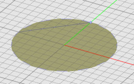
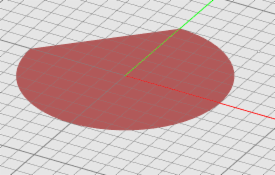
Selecting the two points of the slice line on the edges of a circle strip object.
Selecting the split point on a curve object.
Polygonize Tool
![]() Menu → Tools → Basic → Polygonize
Menu → Tools → Basic → Polygonize
KEYBOARD SHORTCUT: I
FUNCTION: Discretizes the boundary of a curve object or a curved planar surface object into linear segments.
TO POLYGONIZE OBJECT(S):
- Activate the Polygonize Tool.
- Click on the object(s) you want to polygonize one by one and press the Enter Key when done.
- The discretized versions of the selected objects appears in the project workspace.
- A dialog pops up on the lower right corner of the screen where you can modify the side length of the resulting polygonal objects.
- Make sure to click the Enter Key to finalize the operation.
The Polygonize Tool converts a surface object into a polystrip and converts a curve object into a polyline.
SPECIAL CASES OR EXCEPTIONS: You cannot polygonize solid objects.
PYTHON COMMAND:
polygonize(object,side_length)
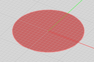
A circle strip to be polygonized.
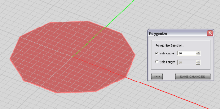
The polygonized version of the circle strip as the default ten-sided polystrip.
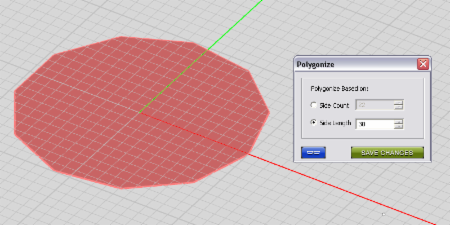
The polygonized version of the circle strip with a side length of 30 units.
Polymesh Tool
![]() Menu → Tools → Basic → Polymesh
Menu → Tools → Basic → Polymesh
KEYBOARD SHORTCUT: P
FUNCTION: Discretizes one or more surface or solid objects into a set of triangular cells
TO POLYMESH AN OBJECT SELECTION:
- Activate the Polymesh Tool.
- Click on the object(s) you want to polymesh one by one and press the Enter Key when done.
- Discretized versions of the selected objects appear in the project workspace.
- A dialog pops up on the lower right corner of the screen which, allows you to change the edge length of the triangular cells.
- Make sure to click the OK button of Polymesh Dialog to finalize the operation.
Naturally, a solid object is turned into a closed polymesh (or a solid polymesh), while a surface object is converted to an open polymesh (or a surface polymesh). Each polymesh object is made up of a number of nodes, edges and faces.
SPECIAL CASES OR EXCEPTIONS: You cannot use the Polymesh Tool with curve objects.
PYTHON COMMAND:
N/A
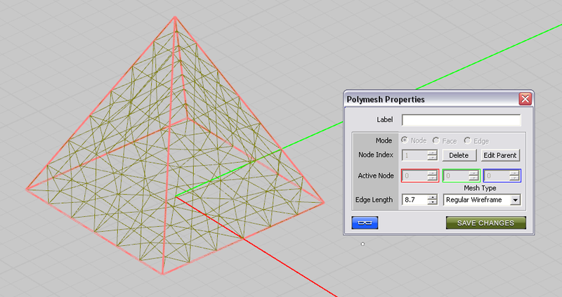
Converting a pyramid to a polymesh object.
Editing a Polymesh Object
After you convert an object to a polymesh, you can edit its properties through the polymesh's property dialog. You can change the mesh type from Regular to Structured and vice versa from the dropdown list labeled Mesh Type. You can also change the Edge Length to increase or decrease the mesh resolution. All the nodes, faces and edges of a polymesh can be accessed for further editing.
Accessing a Polymesh Node
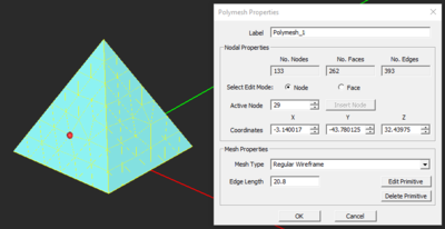
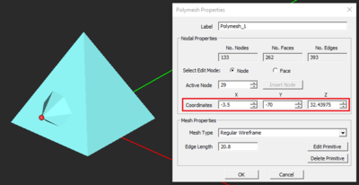
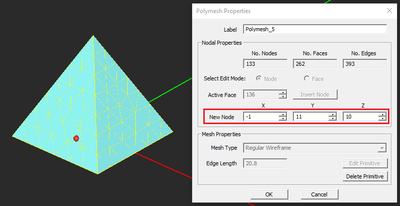
In the section labeled Mode select the Node radio button. A small red ball is placed at the location of Node 1 of the polymesh object. In the box labeled Node Index you can use the spin buttons to cycle through all the nodes. You may also type in the value of a specific node index. When the mouse focus on the node index box, you can use the keyboard's Up Arrow Key and Down Arrow Key to increment or decrement the selected node index. You can also mouse-over any node to highlight it and then click on it to select it. The world coordinates of the active (selected) node are displayed in the property dialog. You can change these values and fine tune the position of any node. You can also delete the selected node by clicking the Delete button next to the node index.
Selecting a node of a polymesh object and editing its coordinates.
Accessing a Polymesh Face
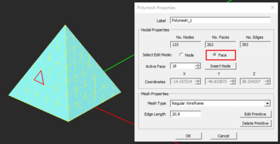
In the section labeled Mode select the Face radio button. The perimeter of Face 1 of the polymesh object is highlighted as a red triangle. In the box labeled Face Index you can use the spin buttons to cycle through all the faces. You may also type in the value of a specific face index. When the mouse focus on the face index box, you can use the keyboard's Up Arrow Key and Down Arrow Key to increment or decrement the selected face index. You can also mouse-over any face and click on its surface to select it. You can insert a new node at the centroid of the selected face. To do so, click the Insert button next to the face index. A new node is created at the centroid of the selected face. Note that the selected face is now transformed into three smaller faces. You have the opportunity to change the location of the newly inserted node at this time. EM.CUBE establishes a temporary local coordinate system at the centroid of the selected face with the local X-axis parallel to the first edge of the selected face and the local Z-axis normal to the plane of the selected face. The three active node coordinate boxes in this case represent the offset coordinates of the New Node. You can either use the spin buttons or type in new offset values to modify the location of the new node.
Selecting a face of a polymesh object and inserting a new node at the face centroid.
Accessing a Polymesh Edge
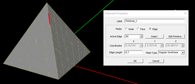
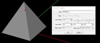
In the section labeled Mode select the Edge radio button. The Edge 1 of the polymesh object is highlighted as a red line segment. In the box labeled Edge Index you can use the spin buttons to cycle through all the edges. You may also type in the value of a specific edge index. When the mouse focus on the edge index box, you can use the keyboard's Up Arrow Key and Down Arrow Key to increment or decrement the selected edge index. Note that polymesh edges cannot be selected by mouse. You can insert a new node at the midpoint of the selected edge. To do so, click the Insert button next to the edge index. A new node is created at the midpoint of the selected edge. Note that the insertion of a new node at the selected edge splits the two triangular faces sharing that edge into four new smaller faces. You have the opportunity to change the location of the newly inserted node at this time. EM.CUBE establishes a temporary local coordinate system at the midpoint of the selected edge with the local X-axis parallel to the selected edge and the local Z-axis normal is aligned along the average of the normal vectors of the two triangular faces sharing that edge. The three active node coordinate boxes in this case represent the offset coordinates of the New Node. You can either use the spin buttons or type in new offset values to modify the location of the new node.
Selecting an edge of a polymesh object and inserting a new node at the edge midpoint.
Consolidate Tool
![]() Menu → Tools → Basic → Consolidate
Menu → Tools → Basic → Consolidate
KEYBOARD SHORTCUT: None
FUNCTION: Converts open polymesh objects to generic surface objects and converts closed polymesh objects to generic solid objects
TO CONSOLIDATE AN OBJECT SELECTION:
- Activate the Consolidate Tool.
- Click on the polymesh object(s) you want to consolidate one by one and press the Enter Key when done.
- Generic surface of solid versions of the selected polymesh objects appear in the project workspace.
SPECIAL CASES OR EXCEPTIONS: You can also use the Consolidate Tool to convert Boolean objects to generic surface or solid objects. In that case, you will lose access to the properties of the individual constituents of the original Boolean object.
PYTHON COMMAND:
N/A
Spline Tool
![]() Menu → Tools → Basic → Spline Fit
Menu → Tools → Basic → Spline Fit
KEYBOARD SHORTCUT: None
FUNCTION: Creates smooth cubic-spline interpolated versions of one or more discretized (polystrip, polyline or polymesh) objects
TO SPLINE-FIT AN OBJECT SELECTION:
- Activate the Spline Fit Tool.
- Click on the object(s) you want to consolidate one by one and press the Enter Key when done.
- Generic surface of solid versions of the selected polymesh objects appear in the project workspace.
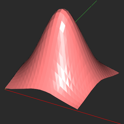
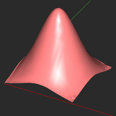
The Spline Fit Tool converts a polyline to a NURBS curve with the same nodes and converts a polystrip to a NURBS strip with the same nodes. In the case of a polymesh object, the Spline Fit Tool creates a smooth generic surface object version. The latter case doesn't always yield satisfactory results due to the complexity of spline fit operation for arbitrary nodal surfaces. In some cases, the Gibbs effect may produce undesirable overshoot spikes at the boundary of the surface object.
SPECIAL CASES OR EXCEPTIONS: The Spline Fit Tool doesn't work with close of solid polymesh objects.
PYTHON COMMAND:
N/A
A surface polymesh object (left) and its spline-fitted version (right).
Roughen Tool
![]() Menu → Tools → Basic → Roughen
Menu → Tools → Basic → Roughen
KEYBOARD SHORTCUT: None
FUNCTION: Converts the surface of an object into a random rough surface
TO ROUGHEN AN OBJECT SELECTION:
- Activate the Roughen Tool.
- Click on the object(s) you want to roughen one by one and press the Enter Key when done.
- The Rough Surface Dialog opens up on the lower right corner of the screen. Enter values for the RMS height and correlation length of the rough surface.
- Click the OK button of the dialog to close it and complete the transformation.
SPECIAL CASES OR EXCEPTIONS: The Roughen Tool doesn't work with curve objects.
PYTHON COMMAND:
roughen(label,object,rms_height,corel_Length)

