Difference between revisions of "EM.Ferma"
(→Simulation Examples / Gallery) |
(→2D Solution Planes in EM.Ferma) |
||
| Line 64: | Line 64: | ||
== 2D Solution Planes in EM.Ferma == | == 2D Solution Planes in EM.Ferma == | ||
| + | [[Image:qstatic.png|thumb|300px|Setting up a Transmission Line simulation.]] | ||
EM.Ferma features a 2D solution mode where the model is treated as a longitudinally infinite structure at a list of specified 2D planes. The 2D planes are defined by a Field Sensor definition that already exists in the project. | EM.Ferma features a 2D solution mode where the model is treated as a longitudinally infinite structure at a list of specified 2D planes. The 2D planes are defined by a Field Sensor definition that already exists in the project. | ||
Revision as of 18:47, 4 March 2014
EM.Ferma is EM.CUBE's 3D electrostatic and quasi-static solver.
With EM.Ferma, one can explore the fields in the vicinity of charge distributions, voltage sources, and current sources. Transmission line characteristic impedance (Z0) and Effective Epsilon can also be obtained.
Contents
Methods Of Electrostatics & Quasistatics
In EM.Ferma, we solve the Laplace equation (shown below) subject to specified sources and boundary conditions.
[math]\Delta\varphi(\vec r)=-\frac{\varrho(\vec r)}{\varepsilon_0}[/math]
Once the potential is computed, the electric fields can easily be computed via:
EM.Ferma can also compute magnetic fields from simple line sources via the Biot-Savart Law:
[math] \mathbf{B} = \frac{\mu_0}{4\pi}\int_C \frac{I d\mathbf{l} \times \mathbf{\hat r}}{|\mathbf{r}|^2}[/math]
Sources in EM.Ferma
For static analysis, the model can be excited with any number of Voltage Sources, Charge Sources, or Current Sources. For Quasistatic analysis, only Voltage Sources are of use.
Voltage Sources
In EM.Ferma, Voltage Sources are applied to a specified PEC group that exists under Physical Structure in EM.CUBE's navigation tree. All CAD objects under the specified PEC group will act as Voltage Sources.
To add a new Voltage Source to a project, right-click on Voltage Sources on the navigation tree, and select "Insert Voltage Source...". In the Voltage Source dialog, select the PEC group to which the specified voltage will be applied. Enter any string as the Voltage -- a text string will be interpreted as a variable which can be used for parametric design, or a parameter sweep.
Charge Sources
Charge Sources in EM.Ferma apply a charge (or charge density) to a region defined by any of EM.CUBE's CAD objects.
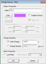
Adding a new Charge Source is very similar to adding a new material in EM.CUBE. Find the Charge Source group label in the navigation tree and select "Insert New Charge Source..." A dialog will prompt the user to decide whether charge for this group will be defined in terms of total charge or charge density. If charge density is chosen, the specified charge density will be applied to all CAD objects defined in the present Charge Source group. If total charge is selected, the specified total charge will be distributed amongst the total volume of all objects under the present material group.
Current Sources
Current Sources in EM.Ferma apply a specified current to any number of one-dimensional CAD objects, such as Lines, Polylines, or Spirals. For any curve, such as a Parabola or a Circle, the user will be prompted to perform a one-time conversion to a Polyline just before running a simulation.
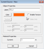
Adding a new Current Source is very similar to adding a new Charge Source. Keep in mind only one-dimensional objects can be drawn under this material group.
Domain and Boundary Conditions
In EM.Ferma, the Laplace equation is solved subject to specified boundary conditions. Here, we will discuss how to specify these boundary conditions.
3D Domain
EM.Ferma's computational domain defines where the boundary condition will be specified. It can be seen in figure 1 as a green cubic wireframe that surrounds all of the CAD objects in the model. To modify the domain boundary, find the "3D Static Domain" entry in the navigation tree, right-click on it, and select "Domain Settings...". The domain dialog will appear. In the domain dialog, the domain boundary can be specified in terms of either a custom, fixed location, or as custom offsets from CAD objects in the scene.
Boundary Condition
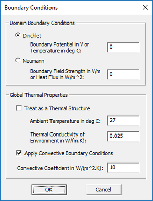
EM.Ferma allows the user to either specify the potential on the boundary (Dirichlet boundary condition), or specify the normal derivative on the boundary (Neumann boundary condition) via a specified field strength. To modify the boundary condition, find "Boundary Conditions" on the navigation tree, and select "Boundary Conditions...". The user will be prompted with the dialog seen in figure.
2D Solution Planes in EM.Ferma
EM.Ferma features a 2D solution mode where the model is treated as a longitudinally infinite structure at a list of specified 2D planes. The 2D planes are defined by a Field Sensor definition that already exists in the project.
To explore EM.Ferma's 2D mode, right-click on "2D Solution Planes" in the navigation tree and select "2D Domain Settings...". In the 2D Static Domain dialog, enable the checkbox labeled "Treat Structure as Longitudinally Infinite across Each 2D Plane Specified Below". You are then able to Add or Edit 2D solution plane definitions to the solution list.
Setting up a Transmission Line Simulation
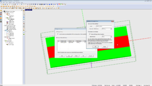
To perform a transmission line simulation, check the Quasistatic simulation mode for a selected 2D plane, as shown in Figure... If an analysis is run with this option checked, the characteristic impedance (Z0) and Effective Epsilon will be computed for the transmission line. This output can be found in appropriately-named text files in the project directory upon completion of the simulation. Fields and potentials at the selected 2D plane will still be computed.
Quasistatic analysis can only be performed with a Dirichlet boundary condition with 0V specified on the boundaries.
For a step-by-step demonstration (including transmission line optimization), take a look at this video on our YouTube channel: EM.CUBE Microstrip Optimization
Simulation Examples / Gallery
Version History
- First available in EM.CUBE 14.2

