Difference between revisions of "EM.Ferma"
Kazem Sabet (Talk | contribs) (→The 2D Electrostatic Simulation Mode) |
Kazem Sabet (Talk | contribs) (→The 2D Electrostatic Simulation Mode) |
||
| Line 285: | Line 285: | ||
[[Image:Info_icon.png|40px]] Click here to learn more about the theory of '''[[Modeling_Lumped_Elements,_Circuits_%26_Devices_in_EM.Cube#2D_Quasi-Static_Solution_of_Transmission_Lines | 2D Quasi-Static Analysis of Transmission Lines]]'''. | [[Image:Info_icon.png|40px]] Click here to learn more about the theory of '''[[Modeling_Lumped_Elements,_Circuits_%26_Devices_in_EM.Cube#2D_Quasi-Static_Solution_of_Transmission_Lines | 2D Quasi-Static Analysis of Transmission Lines]]'''. | ||
| − | [[Image:Info_icon.png|40px]] Click here to learn more about the theory of '''[[Modeling_Lumped_Elements,_Circuits_%26_Devices_in_EM.Cube | + | [[Image:Info_icon.png|40px]] Click here to learn more about the theory of '''[[Modeling_Lumped_Elements,_Circuits_%26_Devices_in_EM.Cube#Modeling_Transmission_Lines_Using_EM.Ferma | Modeling Transmission Lines Using EM.Ferma]]'''. |
The quantities ε<sub>eff</sub> and Z<sub>0</sub> are two of EM.Ferma's standard output [[parameters]]. You can use them to optimize a transmission line structure. Two possible objectives are "Z<sub>0</sub> == 50" or "sqrt(ε<sub>eff</sub>) == 1.5". | The quantities ε<sub>eff</sub> and Z<sub>0</sub> are two of EM.Ferma's standard output [[parameters]]. You can use them to optimize a transmission line structure. Two possible objectives are "Z<sub>0</sub> == 50" or "sqrt(ε<sub>eff</sub>) == 1.5". | ||
Revision as of 03:31, 10 August 2015
Contents
EM.Ferma Primer
EM.Ferma in a Nutshell
EM.Ferma is a 3D static solver. It features two distinct electrostatic and magnetostatic simulation engines that can be used to solve a variety of static and low-frequency electromagnetic problems. Both simulation engines are based on finite difference solutions of Poisson's equation for electric and magnetic potentials.
With EM.Ferma, you can explore the electric fields due to volume charge distributions or fixed-potential perfect conductors, and magnetic fields due to wire or volume current sources and permanent magnets. Your structure may include dielectric or magnetic (permeable) material blocks. You can also use EM.Ferma's 2D quasi-static mode to compute the characteristic impedance (Z0) and effective permittivity of transmission line structures with complex cross section profiles.
| |
EM.Ferma is the low-frequency Static Module of EM.Cube, a comprehensive, integrated, modular electromagnetic modeling environment. EM.Ferma shares the visual interface, 3D parametric CAD modeler, data visualization tools, and many more utilities and features collectively known as CubeCAD with all of EM.Cube's other computational modules. |
![]() Click here to learn more about EM.Cube Modeling Environment.
Click here to learn more about EM.Cube Modeling Environment.
![]() Click here to learn more about the basic functionality of CubeCAD.
Click here to learn more about the basic functionality of CubeCAD.
Static Modeling Methods
![]() Click here to learn more about the theory of Electrostatic and Magnetostatic Methods.
Click here to learn more about the theory of Electrostatic and Magnetostatic Methods.
Defining the Physical Structure in EM.Ferma
The simplest static problems involve a charge source in the free space that produces an electric field, or a current source in the free space that produces a magnetic field. In such cases, the only applicable boundary conditions are defined at the computational domain boundary. As soon as you introduce a dielectric object next to a charge source or a magnetic (permeable) material next to a current source, you have to deal with a complex boundary value problem. In other words, you need to solve the electric or magnetic Poisson's equation subject to the domain boundary conditions as well as material interface boundary conditions. EM.Ferma used the Finite Difference technique for numerical solution of your static boundary value problem.
A Note on Material and Source Types in EM.Ferma
In EM.Cube's other modules, material types are specified under the "Physical Structure" section of the navigation tree, and sources are organized under a separate "Sources" section. In those modules, the physical structure and its various material types typically represent all the CAD objects you draw in your project. Sources are virtual entities that might be associated with certain physical objects and provide the excitation of your boundary value problem.
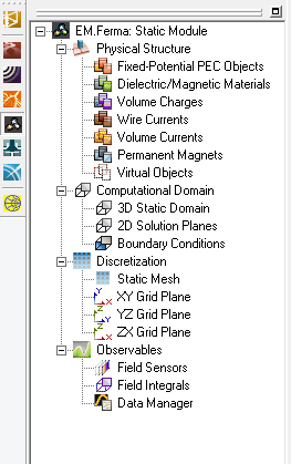
In EM.Ferma, materials and sources are all listed under the "Physical Structure" section of the navigation tree. In other words, there is no separate "Sources" section. For example, you can define default zero-potential perfect electric conductors (PEC) in your project to model metal objects. You can also define fixed-potential PEC objects with a nonzero voltage, which can effectively act as a voltage source for your boundary value problem. In this case, you will solve the Lapalce equation subject to the specified nonzero potential boundary values. Both types of PEC objects are defined from the same PEC node of the navigation tree by assigning different voltage values. Charge and current sources are defined as CAD objects, and you have to draw them in the project workspace just like other material objects.
Grouping Objects by Material or Source Type
Your physical structure in EM.Ferma is typically made up of some kind of source either in the free space or in the presence of one or more material objects. EM.Ferma's electrostatic and magnetostatic simulation engines then discretize these source and material objects and solve the Laplace or Poisson equations to find the electric or magnetic fields everywhere in the computational domain.
All the CAD objects in the project workspace are organized together into object groups which share the same properties including color and electric or magnetic parameters. Once a new object group node has been created on the navigation tree, it becomes the "Active" object group of the project workspace, which is always listed in bold letters. When you draw a new CAD object such as a Box or a Sphere, it is inserted under the currently active surface type. There is only one object group that is active at any time. Any group can be made active by right clicking on its name in the navigation tree and selecting the Activate item of the contextual menu. It is recommended that you first create object groups, and then draw new objects under the active surface group. However, if you start a new EM.Ferma project from scratch, and start drawing a new object without having previously defined any object groups, a new default PEC object group is created and added to the navigation tree to hold your new CAD object.
![]() Click here to learn more about Defining a New Object Group.
Click here to learn more about Defining a New Object Group.
![]() Click here to learn more about Moving Objects among Different Groups.
Click here to learn more about Moving Objects among Different Groups.
Variety of Material Objects
EM.Ferma offers the following types of material objects for construction of your physical structure:
- Perfect Electric Conductors (PEC): A perfect electric conductor (PEC) is a material with εr = 1 and σ = ∞.
- Dielectric/Magnetic Materials: You can define dielectric materials with the relative permittivity εr and electric conductivity σ for electrostatic analysis or magnetic (permeable) materials with the relative permeability μr for magnetostatic analysis.
![]() Click here for a general discussion of Defining Materials in EM.Cube.
Click here for a general discussion of Defining Materials in EM.Cube.
| |
You can define any solid or surface object as a fixed-potential PEC object. |
| |
Excluding surface and curve CAD objects, you can define any solid CAD object as a dielectric or magnetic material object. |
Variety of Source Objects
EM.Ferma also offers the following types of source objects for excitation of your physical structure:
- Fixed-Potential PEC Objects
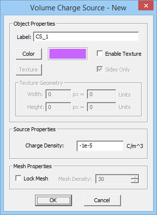
- Volume Charges: For volume charge sources you need to specify a positive or negative charge density in C/m3. You can draw all kinds of solid CAD objects under this group.
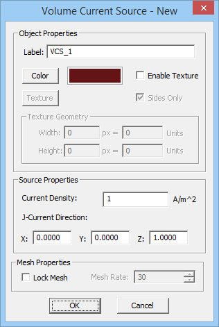
- Volume Currents: For volume current sources you need to specify a current density in A/m2. You can draw all kinds of solid CAD objects under this group. Note that current density is a vectorial quantity and has a magnitude and a unit direction vector.
- Wire Currents
- Permanent Magnets
Using Fixed-Potential PEC Objects as Voltage Sources
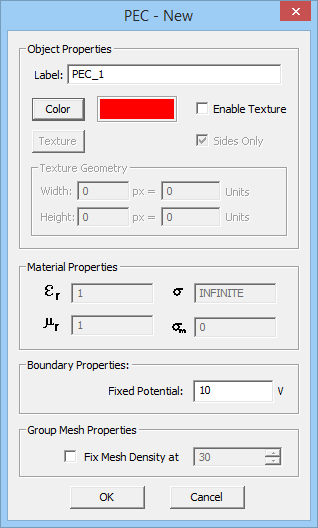
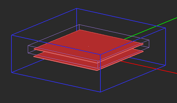
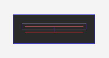
Under the static condition, every point on a PEC object has the same electric potential. By default, this is a zero potential, meaning the PEC object is "grounded". In EM.Ferma, a PEC group has a Fixed Potential' property, which is expressed in Volts and has a zero default value. If you define a new PEC group and keep its default zero voltage, the objects belonging to that group will simply act as metal objects of your physical structure. However, you can define a nonzero voltage value for a PEC group. You can do in the property dialog of the PEC group, which you can access by right-clicking on the group's name in the navigation tree and selecting Properties... from the contextual menu. In the case of a nonzero voltage, all the PEC objects belonging to that group effectively turn into voltage sources. For example, two parallel PEC plates, one with a zero potential and the other with a nonzero potential represent a simple air-filled capacitor. Note that the voltage value can be positive or negative.
Wire Current Sources
EM.Ferma allows you to define idealized wire current sources. You can use this source type to model filament currents or coils. Wire currents are defined using only line and polyline objects. You also need to define a current value I in Amperes and a wire radius r in the project units. The line or polyline object is then approximated as a volume current with a current density of J = I/(πr2) flowing along the line or polyline side's direction. All the wire current sources belonging to the same group have the same color, same current value and same wire radius. The direction of the current can be reversed in wire current sources.
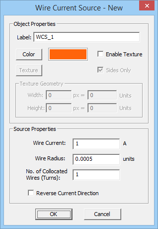
To add a new wire current source group to a project, right-click on "Wire Currents" on the Navigation Tree, and select "Insert New Current Source..." From the Wire Current Source Dialog, you can change the default brown color of the source group or set the values of the Current and Wire Radius. There is also a check box for "Reverse Current Direction". Note that this will reverse the direction of all the wire currents belonging to the same group. When you draw a line or polyline object under a wire current group in the Navigation Tree, you will notice that direction arrows are placed on the drawn CAD object. You can draw any curve object in the project workspace and convert it to a polyline using EM.Cube's Polygonize Tool.
| |
If you draw curve CAD objects under a wire current group, they will be permanently converted to polyline objects before running the simulation engine. |
Permanent Magnets
A permanent magnet is typically a ferromagnetic material with a fixed inherent magnetization vector. As a result, it can be used as a source in an magnetostatic problem. When a permeable material has a permanent magnetization, the following relationship holds:
[math] \mathbf{B(r)} = {\mu} (\mathbf{H(r)} + \mathbf{M(r)} ) [/math]
where M(r) is the magnetization vector. In SI units system, the magnetic field H and magnetization M both have the same units of A/m.
It can be shown that for magnetostatic analysis, the effect of the permanent magnetization can be modeled as an equivalent volume current source:
[math] \mathbf{J_{eq}(r)} = \nabla \times \mathbf{M(r)} [/math]
If the magnetization vector is uniform and constant inside the volume, then its curl is zero everywhere inside the volume except on its boundary surface. In this case, the permanent magnetic can be effectively modeled by an equivalent surface current density on the surface of the permanent magnetic object:
[math] \mathbf{J_{s,eq}(r)} = \mathbf{M(r)} \times \hat{\mathbf{n}} [/math]
where [math] \hat{\mathbf{n}} [/math] is the unit outward normal vector at the surface of the permanent magnet object. Note that the volume of the permanent magnet still acts as a permeable material in the magnetostatic analysis.
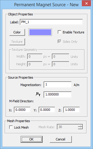
To add a new permanent magnet source group to a project, right-click on "Permanent Magnets" on the Navigation Tree, and select "Insert New Permanent Magnet Source..." From the Permanent Magnet Source Dialog, you can change the default purple color of the source group or set the values of the relative permeability, Magnetization magnitude and unit direction vector components. The default direction vector is z-directed.
Computational Domain and Discretization
The Domain Box
In EM.Ferma, the Poisson or Laplace equations are solved subject to boundary conditions using the Finite Difference technique. As a result, you need to specify a finite computational domain and then specify the domain boundary conditions. EM.Ferma's computational domain defines where the domain boundary condition will be specified. A default domain box is always placed in the project workspace as soon as you draw your first object. The domain can be seen as a blue cubic wireframe that surrounds all of the CAD objects in the project workspace.
To modify the domain settings, click the Domain button of the Simulate Toolbar or right-click on "3D Static Domain" entry in the Navigation Tree and select "Domain Settings..." from the contextual menu. In the Domain Settings Dialog, the computational domain can be defined in two different ways: Default and Custom. The default type places an enclosing box with a specified offset from the largest bounding box of your project's CAD objects. The default offset value is 20 project units, but you can change this value arbitrarily. The custom type defines a fixed domain box by specifying the coordinates of its two opposite corners labeled Min and Max in the world coordinate system.
Domain Boundary Conditions
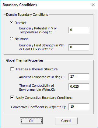
EM.Ferma allows you to specify the electric potential boundary conditions on the domain box. Two options are available. The Dirichlet boundary condition is the default option and is specified as a fixed potential value on the surface of the domain walls. By default, this value is 0 Volts. The Neumann boundary condition specifies the normal derivative of the electric scalar potential on the surface of the domain walls. This is equivalent to the normal electric field component on the domain walls and its value is specified in V/m. The magnetostatic simulation engine always assumes Dirichlet domain boundary conditions and sets the values of the magnetic vector potential to zero on all the domain walls. To modify the boundary conditions, right-click on "Boundary Conditions" in the Navigation Tree, and select "Boundary Conditions..." from the contextual menu to open the Boundary Conditions Dialog.
The Static Mesh
The Finite Difference technique discretizes the computational domain using a 3D rectangular grid. EM.Ferma generates a fixed-cell mesh. This means that the extents of the mesh cells along the principal axes are fixed: Δx, Δy, Δz. By default, the mesh cell size is set to one unit project along all the three directions (with Δx = Δy = Δz). To modify the cell size, click the Mesh Settings button of the Simulate Toolbar or right-click on "Static Mesh" in the Navigation Tree, and select "Mesh Settings..." from the contextual menu to open the Mesh Settings Dialog.
| |
To obtain accurate results, it is highly recommended to use a square mesh as much as possible. |
Running Static Simulations in EM.Ferma
Two Simulation Engines
EM.Ferma has two independent but functionally similar static simulation engines: Electrostatic and Magnetostatic. The electrostatic engine solves the electric form of Poisson's equation for electric scalar potential subject to electric field boundary conditions, in the presence of electric sources (volume charges and fixed-potential PEC blocks) and dielectric material media. The magnetostatic engine solves the magnetic form of Poisson's equation for magnetic vector potential subject to magnetic field boundary conditions, in the presence of magnetic sources (wire and volume currents and permanent magnetic blocks) and magnetic material media.
In EM.Ferma you don't have to select any specific simulation engine. The program looks at the types sources and material objects present in your project workspace and then it determines whether an electrostatic analysis or a magnetostatic analysis or possibly both should be performed. When there are only electric sources present, you will get nonzero electric fields and zero magnetic fields. When there are only magnetic sources present, you will get nonzero magnetic fields and zero electric fields.
To run a static simulation, first you have to open the Run Dialog. This is done by clicking the "Run" button of the Simulate Toolbar, or by selecting the "Run" item of the Simulate Menu, or simply using the keyboard shortcut "Ctrl+R". The only available simulation engine is "Static". Clicking the Run button of this dialog starts a static analysis. A separate window pops up which reports the progress of the current simulation.
Simulation Modes
EM.Ferma currently offers three different simulation modes: Analysis, Parametric Sweep and Optimization. An "Analysis" is a single-shot finite difference solution of your static structure. The structure is first discretized using a fixed-cell mesh and the Poisson equation is solved numerically everywhere in your computational domain. The field and potential values at each mesh node are computed and the specified observables are written into data files.
In a "Parametric Sweep", one ore more variables are varied at the specified steps(s). This means that you must first define one or more variables in your projects. Variables can be associated with CAD object properties like dimensions, coordinates, rotation angles, etc. or with material properties or source properties. For each single variable sample or each combination of variable samples, first all the associated CAD object properties, material properties or source properties are updated in the project workspace. Then is a finite difference solution of your updated static structure is computed and parametric sweep proceeds to the next variable sample or combination.
The optimization mode requires definition of one or more objectives based on the standard output quantities. At the present time, the optimization mode is only available for the 2D Quasi-Static Mode of the EM.Ferma, which will be discussed separately later.
Static Simulation Engine Settings
EM.Ferma currently uses a single iterative linear system solver based on the stabilized Bi-Conjugate Gradient (BiCG) method to solve the matrix equations which result from the discretization of Poisson's equation. You can specify some numerical parameters related to the Bi-CG solver. To do that, you need to open the Simulation Engine Settings Dialog by clicking the "Settings" button located next to the "Select Engine" drop-down list. From this dialog you can set the maximum number of BiCG iterations, which has a default value of 10,000. You can also set a value for "Convergence Error". The default value for electrostatic analysis is 0.001. For magnetostatic analysis, the specified value of convergence error is reduced by a factor 1000 automatically. Therefore, the default convergence error in this case is 1e-6.
Working with Static Simulation Data
At the end of an electrostatic simulation, the electric field and electric scalar potential values are computed at all the mesh grid points of the entire computational domain. At the end of an magnetostatic simulation, the magnetic field and magnetic vector potential values are computed at all the grid nodes. The field and potential values are written into output data files and can be visualized on the screen only if you define a field sensor observable. In the absence of a defined observable, the static simulation will be carried out and completed, but to action will take place.
Defining Field Sensors
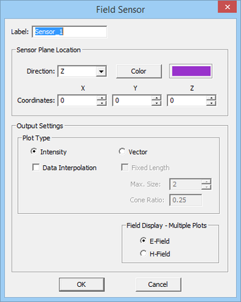
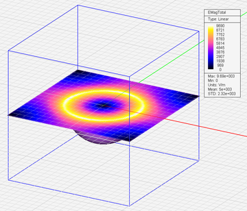
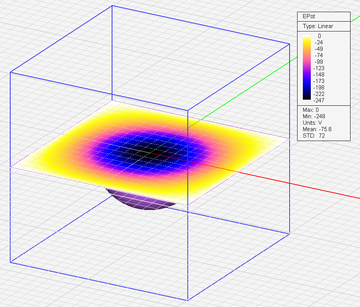
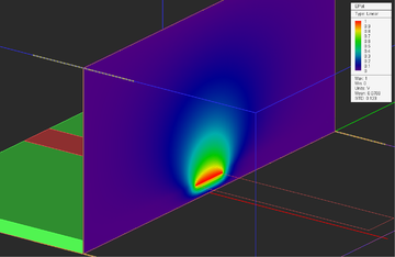
Just like other EM.CUBE Modules, EM.Ferma has a Field Sensor observable, which plots 3D visualizations of electric and magnetic field components on a specified plane. However, unlike the other modules, EM.Ferma field sensors have two additional plots for electric scalar potential and magnitude of the magnetic vector potential. These are called the "EPot" and "HPot" nodes on the navigation tree. To define a Field Sensor, right-click on "Field Sensors" in the Navigation Tree and select "Insert New Observable..." from the contextual menu. The Field Sensor dialog allows the user to select the direction of the sensor (X, Y, Z), visualization type, and whether E-field output or H-field output will be shown during a sweep analysis. The E-fields and H-fields are computed at each mesh node within the specified 2D Field Sensor plane. In other words, the resolution of the Field Sensor is controlled by the mesh resolution.
![]() Click here to learn more about defining Field Sensor Observables.
Click here to learn more about defining Field Sensor Observables.
![]() Click here to learn more about Visualizing 3D Near-Field Maps.
Click here to learn more about Visualizing 3D Near-Field Maps.
![]() Click here to learn more about Plotting Field Distribution Graphs Along Lines.
Click here to learn more about Plotting Field Distribution Graphs Along Lines.
Defining Field Integrals
It is often needed to compute integrals of the electric or magnetic fields to define other related quantities. The following table shows some of widely used field integrals in electrostatics and magnetostatics. In EM.Ferma, you can define a path integral along a line segment that is parallel to one of the three principal axes, or a loop integral on a rectangle that is parallel to one of the principal planes. You can also define flux planes or flux boxes. All this is done from the same Field Integral Dialog. To define a Field Integral, right-click on "Field Integrals" in the Navigation Tree and select "Insert New Observable..." from the contextual menu. The Integral Type drop-down list gives nine options as listed in the table below:
| Field Integral | Definition | Output Data File |
|---|---|---|
| Voltage | [math] V = - \int_C \mathbf{E(r)} . \mathbf{dl} [/math] | voltage.DAT |
| Current | [math] I = \oint_{C_o} \mathbf{H(r)} . \mathbf{dl} [/math] | current.DAT |
| Conduction Current | [math] I_{cond} = \int\int_S \mathbf{J(r)} . \mathbf{ds} = \int\int_S \sigma \mathbf{E(r)} . \mathbf{ds} [/math] | conduction_current.DAT |
| Electric Flux | [math] \Phi_E = \int\int_{S_o} \mathbf{D(r)} . \mathbf{ds} = \int\int_{S_o} \epsilon \mathbf{E(r)} . \mathbf{ds} [/math] | flux_E.DAT |
| Magnetic Flux | [math] \Phi_H = \int\int_S \mathbf{B(r)} . \mathbf{ds} = \int\int_S \mu \mathbf{H(r)} . \mathbf{ds} [/math] | flux_H.DAT |
| Electric Energy | [math] W_E = \frac{1}{2} \int \int \int_V \epsilon \vert \mathbf{E(r)} \vert ^2 dv [/math] | energy_E.DAT |
| Magnetic Energy | [math] W_H = \frac{1}{2} \int\int\int_V \mu \vert \mathbf{H(r)} \vert ^2 dv [/math] | energy_H.DAT |
| Ohmic Power Loss | [math] P_{ohmic} = \int\int\int_V \sigma \vert \mathbf{E(r)} \vert ^2 dv [/math] | ohmic.DAT |
| Resistance | [math] R = V/I_{cond} = - \int_C \mathbf{E(r)} . \mathbf{dl} / \int\int_S \sigma \mathbf{E(r)} . \mathbf{ds} [/math] | resistance.DAT |
| Capacitance | [math] C = \Phi_E/V = \int\int_{S_o} \epsilon \mathbf{E(r)} . \mathbf{ds} / \int_C \mathbf{E(r)} . \mathbf{dl} [/math] | capacitance.DAT |
| Self-Inductance | [math] L = \Phi_H/I = \int\int_S \mu \mathbf{H(r)} . \mathbf{ds} / \oint_{C_o} \mathbf{H(r)} . \mathbf{dl} [/math] | inductance.DAT |
| Mutual Inductance | [math] M = \Phi_H^{\prime}/I = \int\int_{S^{\prime}} \mu \mathbf{H(r)} . \mathbf{ds} / \oint_{C_o} \mathbf{H(r)} . \mathbf{dl} [/math] | inductance.DAT |
In the above table, C represents an open curve (path), Co represents a closed curve (loop), S represents an open surface like a plane, So represents a closed surface like a box, and V represents a volume. In the case of mutual inductance, S' represents an open surface or plane passing through the second (coupled) inductor, and Φ'H represents the magnetic flux linkage due to the magnetic field of the first inductor passing through the second inductor.
The domain of the field integral is set using the "Integration Box Coordinates" section of the Field Integral dialog. Box domains are specified by the coordinates of two opposite corners. Voltage Path requires a line; therefore, two of the coordinates of the two corners must be identical. Otherwise, an error message will pop up. For example, (0, 0, 0) for Corner 1 and (10, 0, 0) for Corner 2 define a Z-directed line segment. Current Loop requires a rectangle; therefore, one of the coordinates of the two corners must be identical. For example, (0, 0, 0) for Corner 1 and (10, 10, 0) for Corner 2 define a rectangle in the XY plane.
After the completion of a static simulation, the result of the field integrals are written into ".DAT" data files. These files can be accessed using EM.Cube's Data Manager.
The 2D Electrostatic Simulation Mode
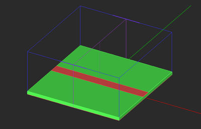
EM.Ferma's electrostatic simulation engine features a 2D solution mode where your physical model is treated as a longitudinally infinite structure in the direction normal to specified "2D Solution Plane". More than one 2D solution plane may be defined. In that case, multiple 2D solutions are obtained. A 2D solution plane is defined based on a "Field Sensor" definition that already exists in your project.
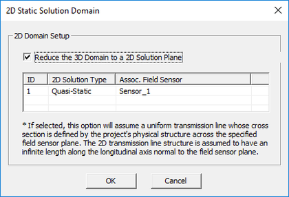
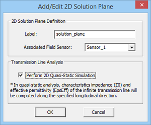
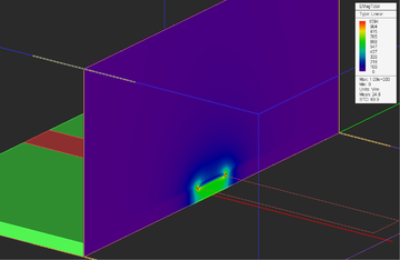
To explore EM.Ferma's 2D mode, right-click on 2D Solution Planes in the "Computational Domain" section of the navigation tree and select 2D Domain Settings... from the contextual menu. In the 2D Static Domain dialog, check the checkbox labeled "Treat Structure as Longitudinally Infinite across Each 2D Plane Specified Below". This would enable you to add new 2D Solution Plane definitions to the list or edit the existing ones. In the Add/Edit 2D Solution Plane dialog, you can choose a name other than the default name and select one of the available field sensor definitions in your project. At the end of a 2D electrostatic analysis, you can view the electric field and potential results on the respective field sensor planes. It is assumed that your structure is invariant along the direction normal to the 2D solution plane. Therefore, your computed field and potential profiles must be valid at all the planes perpendicular to the specified longitudinal direction.
You can also use EM.Ferma to perform a quasi-static analysis of multi-conductor transmission line structures, which usually provides good results at lower microwave frequencies (f < 10GHz). For that purpose, check the box labeled "Perform 2D Quasi-Static Simulation" when defining the 2D solution plane. EM.Ferma computes the characteristics impedance Z0 and effective permittivity εeff of your TEM or quasi-TEM transmission line. The results are written to two output data files named "solution_plane_Z0.DAT" and "solution_plane_EpsEff.DAT", respectively, where "solution_plane" is the default name of your 2D plane. At the end of a quasi-static analysis, the electric field components and scalar potential at the selected 2D planes will still be computed and can be visualized. In the case of a parametric sweep, the data files will contain multiple data entries listed against the corresponding variable samples. Such data files can be plotted in EM.Grid.
![]() Click here to learn more about the theory of 2D Quasi-Static Analysis of Transmission Lines.
Click here to learn more about the theory of 2D Quasi-Static Analysis of Transmission Lines.
![]() Click here to learn more about the theory of Modeling Transmission Lines Using EM.Ferma.
Click here to learn more about the theory of Modeling Transmission Lines Using EM.Ferma.
The quantities εeff and Z0 are two of EM.Ferma's standard output parameters. You can use them to optimize a transmission line structure. Two possible objectives are "Z0 == 50" or "sqrt(εeff) == 1.5".
![]() Click here for a discussion of Optimization in EM.Cube.
Click here for a discussion of Optimization in EM.Cube.
For a step-by-step demonstration (including transmission line optimization), take a look at this video on our YouTube channel: EM.CUBE Microstrip Optimization
Version History
- First available in EM.CUBE 14.2
More Resources

