Analog Tutorial Lesson 5: Creating a New Part from Your Analog Circuit
Creating a New Part from Your Circuit
Contents
Objective
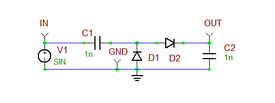
RF.Spice A/D allows you to take a circuit and turn it into a user defined part. Almost any circuit can be turned into a part with just a few steps. The new device is stored in RF.Spice's Parts Database. You can create multiple instances of your new device in any circuit. In this tutorial lesson, you will learn how to use B2.Spice's Device Editor. You will create a voltage multiplier circuit as shown below and then will turn it into a new database device. in this lesson, you will also learn how to set up a parametric sweep in RF.Spice A/D.
Setting Up the Circuit for Part Creation
RF.Spice A/D consists of two separate applications: the Workshop and Device Editor. in this first part of this tutorial lesson, you will build a voltage doubler circuit in the Workshop. Here is a list of the parts needed for your circuit:
| Part Name | Part Type | Part Value |
|---|---|---|
| V1 | Voltage Source | Waveform = Sinusoidal, Amplitude = 5V, Frequency = 1MHz, Offset = 0V |
| C1 | Capacitor | 1n |
| C2 | Capacitor | 1n |
| D1 | Diode | Defaults |
| D2 | Diode | Defaults |
Connect the part as shown in the circuit and place a ground.
Assigning Markers
Markers have many uses in RF.Spice A/D. First and foremost, they are used to identify and label the nodes of a circuit.
| |
If two nodes in a circuit have markers with the same name, then those two nodes are considered to be identical or connected to each other. |
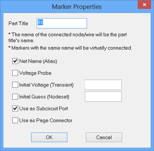
When creating a new part out of your circuit, you need to use markers to designate the input/output nodes or pins of your new device. Markers have several properties. For example, they can be used for designating net names or aliases, or as voltage probes, or as subcircuit ports. To place a marker, you can use the keyboard shortcut "Alt+N" for a Net Marker, "Alt+L" for Voltage Probe Marker, or "Alt+R" for Subcircuit Port Marker, respectively. Or alternatively, you can go to the Markers Submenu of the Parts Menu and pick up one of the several marker types offered. For this lesson, create three Subcircuit Port Markers and label them IN (input port), OUT (output port) and GND (ground). Place your markers as shown in the above figure. Double-click on the markers to open their property dialog as shown in the figure below and change their names.
Running a Transient Test of the Voltage Doubler Circuit
To make sure that your voltage doubler circuit works properly, run a quick transient test with the following parameters:
| Start Time | 0 |
|---|---|
| Stop Time | 10u |
| Linearize Step | 10n |
| Step Ceiling | 10n |
| Preset Graph Plots | v(in_1), v(out_1) |
Run the transient test and you will get a graph like the one shown in the opposite figure. You can see that after 8 microseconds, the output voltage is an almost clean DC of 8.71V. An ideal voltage doubler would produce a DC voltage of 10V. The discrepancy here is due to the junction voltage drops at the two diodes.
Creating the New Part
Before creating your new part, you need to make some decisions. Do you want to create a part that functions a one-port DC voltage source with an internal sinusoidal source? Or do you want to create a signal conditioning device that takes a time varying signal at its input port and generates a doubled DC voltage at its output port? In this lesson, you will choose the latter case. Therefore, you do not need the sinusoidal voltage source as part of your new device. Go ahead and delete it!
At this point, you are ready to create your new part. Go to the Workshop's File Menu and select "Create Part from Circuit...", or simply use the keyboard shortcut "Ctrl+M". The program will then prompt you for a name. Enter the name you wish for the new part, say, "MyVDoubler", and click OK. Then the program will ask if you would like it to create a symbol for your part. If you already have a symbol ready, click NO and Workshop will then ask you to select a symbol from the Parts Database. Otherwise, click YES and Workshop will create a generic box symbol to be used with your new part. The new device "MyVDoubler" is now in the database and you're ready to use it or further customize it.
| |
After you create a new part either from the Workshop or using Device Editor, you need to close the B2.Spice A/D application and re-open it to update the Parts Bin. |
Using Your New Part in a New Circuit
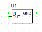
Your new device "MyVDoubler" must by in your Parts Bin and ready to use. Start a new B2.Spice project in the Workshop. Open the Parts Bin in the "Add Part" tab of the Toolbox. Open the "Name" tab and click the letter "M" to display all the part names starting with M. Scroll all the way down to find your new part. Double-click on it and place its ghost on the schematic. You should see a rectangular box like in the figure below.
Keep in mind that since you asked the program to create a symbol for your new device automatically, the new symbol might be far from good-looking (as you can see from the above figure). But don't worry - you can change the symbol and improve its appearance as you will do later. For the time being, you would like to see if your new device functions correctly as you would expect. Double-click the device to open its property dialog as shown in the figure below.
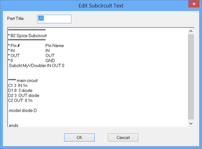
Notice the new symbol appearing in the property dialog of the part. Click the button labeled "Edit Model..." on the right side of the dialog. A new dialog open ups with the title: "Edit Subcircuit Text" as shown in the above figure. Here you see the Netlist code for your model, which is in fact the Netlist representation of your original voltage doubler circuit minus the voltage source. You can edit this Netlist model at any time if you like. Close both dialogs and return to the Schematic Editor.
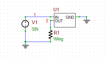
Now, insert a new sinusoidal voltage source with an amplitude of 5V and a frequency of 1MHz identical to the previous section of the lesson. Connect it to the "IN" port of your device. Connect the "GND" pin of your device to the new circuit's ground. At the "OUT" pin of the device, place a large 1M resistor as a sort of "Open" load. Your new circuit should like the figure below:
Run the same transient test as before from 0 to 10 microseconds. This time look for the voltages at nodes 1 and 2. The resulting graph is shown in the opposite figure. It is almost identical to the previous graph that you got when testing your original voltage doubler circuit. Congratulations! Your new device works!!!
Running a Parametric Sweep
The reason you placed a large 1M resistor at the output of your device was to reproduce the same conditions as in your original circuit just for the purpose of verification. Next, you will explore the effect of resistive loading on your device. You will use B2.Spice's "Parametric Sweep" capability for this task. The goal is to vary the resistance of R1 and observe the effect on the output voltage, hoping that your new device still continues to provide a clean DC voltage twice as large as the input amplitude. The test type you will perform is still "Transient" as before.
Bring up the Transient Test from the Tests Toolbox, and set the parameters for the test as follows:
Start Time: 0
Stop Time: 10u
Linearize Step: 10n
Step Ceiling: 10n
Don't forget to uncheck the "Basic" check box of Transient Test from the previous step of this tutorial lesson. Instead, check the middle check box in the "Sweep" column as shown in the figure below. Click on the Setup button to open the Transient Test Setup Dialog, also shown below. Note that this time the "Sweep" tab is active at the lower portion of the dialog.
Click the "Sweep Setup..." button of the dialog to open up the Sweep Settings Dialog as shown in the above figure. This is where you set up all your sweep parameters and their ranges and other properties. In this case, you will sweep the resistance of R1. Note that the top table of the dialog list's all the parts in your circuit along with their individual parameters. For example, you can see the "resistance" of the resistor "r1" and all the specific properties of the sinusoidal voltage source "v1" including its peak amplitude "Va" and frequency "Freq". Click on the first row of the table to highlight the resistance of "r1". In the middle section of the dialog titled "Parameter Setup", you will see the name "r1.resistance". Select the radio button "Sweep Parameter". You will sweep the resistance with the values 1K, 10K, 100K and 1M. So select the "Decade" option for "Interval Type". Set the start and end values at 1k and 1M, respectively, with the number of steps per interval equal to 1. Click the "Accept Changes" button. The sweep parameters with its values now appears in the bottom table. It shows 4 iterations based on the range you just defined.
| |
When you have more than one sweep parameter, you can changes their hierarchical order using the "Move Up" and "Move Down" buttons. The order is important for plotting families of curves. |
Close the Sweep Settings Dialog and return to the Transient Test Setup Dialog. In the "Output Results Options" section of dialog, check the "Graph" box. Open the Edit Plots List Dialog and keep only the output voltage signal v(2) in the Graph table. Click the Run button to run the transient sweep test. The graph shown in the opposite figure will appear at the bottom of the Workshop. It shows the output voltage signal for the successive values of the resistance R1. As you can see, once the resistance falls below 100K, the circuit fails to function properly and ripple start to appear. At R = 1K, the output voltage is a sawtooth waveform with a peak amplitude of only 5V as the sinusoidal input.
Modifying the New Part Using Device Editor
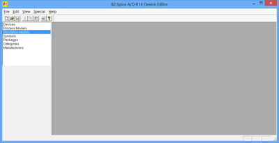
B2.Spice's Device Editor is an independent application, which you can use to access your "Parts Database". You can explore and edit your existing parts, add new parts or import external parts. You can open the Device Editor from the File Menu of the B2.Spice A/D application (the Workshop) by selecting "Open Device Editor..." or simply use the keyboard shortcut "Ctrl+D". The Device Editor opens up in a new separate window with its own Title Bar, Menu Bar and Main Toolbar as shown below.
| |
B2.Spice's parts database file is called "parts.mdb" and is located in the "Documents > b2spice" folder on your C Hard Drive. A copy of your original parts database is also supplied in the B2.Spice A/D installation directory for future references. Sometimes, when trying to open up the Device Editor, you may get a message asking you to locate the parts database. Please make sure you set the correct path in the "Documents" folder. |
Every device in the Part Database has a number of properties and attributes. The most important of these are the "Model" and the "Symbol". A device's model might be a process (technology) model native to Spice or XSpice, or it can be a simulation model defined as a Netlist subcircuit. B2.Spice also provide extensive S-parameter-based models for RF applications. A symbol is a drawing with one, two or more pins that can be connected through wires.
When you create a new part from a circuit just like you did earlier in this tutorial lesson, B2.Spice A/D takes care of a lot of detailed work automatically behind the scene. You can also create a device from the ground up step by step. The side panel on the left of Device Editor allows you to explore the contents of your Parts Database using different criteria. For example, you can view and edit all devices, or just the simulation models, or symbols, etc. Let's first make sure that your new device "MyVDoubler" is in the database. Double-click the "Devices" item on the side panel to open the Select Device Dialog as show below.
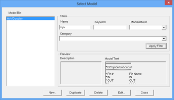
In the "Filers" section of the dialog, in the "Part Name" box, type in the first letter of the name of the device you are searching, say "myv" in this case. Click the "Apply Filter" button, and you will see the name of your device appear in the device bin on the left. You can also see the symbol of your device in the dialog. So your device is there for sure! You can edit your device from this dialog. But let's move on. Close the dialog and double-click the "Simulation Models" item on the side panel. This opens up the Select Model Dialog also shown above. Follow the same procedure and search for your device's name in the Filters section. You will find a simulation model with the same name "MyVDoubler" and you will recognize the first few lines of its Netlist model, which is displayed in this dialog. When B2.Spice A/D created your new device, first it created its simulation model, then created a symbol for it, then matched the model pins with the symbol pins, and finally packaged the whole thing as a device called "MyVDoubler".
Remember that the automatically generated symbol for your device wasn't particularly interesting, especially the fact that the GND (ground) pin was in an awkward location. Now you are going to modify the symbol of your device in the Device Editor. Go back to the Device Editor's side panel and double-click the "Symbols" item. This opens up the Select Symbol Dialog as shown in the figure below.
Using the name filter, search for and find the symbol of "MyVDoubler". Then, click the "Edit Picture" button of the dialog to open up B2.Spice's "Symbol Editor". This is a versatile drawing tool with lots of capabilities. However, most of the time, you will use it for very simple drawings. The middle figure above shows the workspace of Symbol Editor containing your original symbol. The most important part of a symbol is its pins, not its drawing which simply serves a graphical purpose only. Even the text doesn't matter much. Pins are very small squares (looking more like points) that must have unique names. If you double click on a pin, its property dialog pops up, from which your can change the name of that pin. Sometimes, it is difficult to pick a pin when it is connected to the symbol. In that case, you should move the connecting lead or wire slightly to disengage it and then try double-clicking it again. In this lesson, you want to move the "GND" from the left side just underneath the "IN" pin to the right side of the symbol and far under the "OUT" pin. First, move the lead and place it on the right. Then, grab the pin itself and drag it to the right and drop it at the open end of the lower lead as shown in the above figure on the right. Don't forget to save your newly modified drawing. Close the Symbol Editor and then close the Device Editor. You're done! Next time you open B2.Spice A/D and place the "MyVDoubler" part in your circuit, you will see the new improved symbol. It will be much easier to connect to this new one.
