Analog Tutorial Lesson 11: Creating a Reusable Parameterized Subcircuit Device
Creating a Parameterized Subcircuit Part
Contents
- 1 Objective
- 2 Creating a New Three-Pin Symbol
- 3 Creating a Parameterized Subcircuit Model Definition
- 4 Defining a Simulation Model Using Your New Parameterized Subcircuit Model Definition
- 5 Creating a New Device Using Your New Simulation Model
- 6 Using Your New Parameterized Part in a New Circuit
- 7 Verifying Your New Parameterized Subcircuit Model
Objective
Besides offering a large set of native behavioral models, B2.Spice A/D allows you to define many new models and parts using Netlist Subcircuits. Netlist is SPICE's standard programming language. In the previous tutorial lesson, you created a new part from a circuit. Your new device was generated "As Is" with no parameters that you could control in different circuits and applications. Parameterized Subcircuit Parts are based on user defined devices whose behavior can be modified with one or more parameters. The ability to create parameterized subcircuit models and devices is one of B2.Spice's most powerful features. In this tutorial lesson, you will learn how to use B2.Spice's Device Editor to create new versatile parameterized parts, devices and models. Specifically, you will create a resistive bridge network that can be reconfigured as a "Tee" or "Pi" network using a "Type" parameter. All the resistances will be parameterized so you can set and very them in different circuits or even run parametric sweeps. The two bridge types are shown in the figure below:
To create a reconfigurable model, we will combine the two circuits into one as shown in the figure below:
In the above figure, for a Tee bridge, you will set RX1 = R1, RX2 = R2, RX3 = R3 and RX4 = Infinite, whereas for a Pi bridge, you will set RX1 = 0, RX2 = R2, RX3 = R3 and RX4 = R1. Ultimately, you want a three-terminal device as show above on the right.
Creating a New Three-Pin Symbol
As a first step, you will create a three-pin symbol for your bridge device and will save it into the database. Open the Device Editor.
| |
B2.Spice's parts database file is called "parts.mdb" and is located in the "Documents > b2spice" folder on your C Hard Drive. A copy of your original parts database is also supplied in the B2.Spice A/D installation directory for future references. Sometimes, when trying to open up the Device Editor, you may get a message asking you to locate the parts database. Please make sure you set the correct path in the "Documents" folder. |
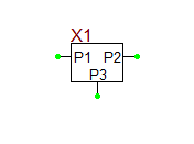
From the File Menu of the Device Editor, select "New Symbol...". This will open up B2.Spice's Symbol Editor with a clean slate as shown in the opposite figure. First, click on the "Pin Tool" ![]() and draw three pins and name them P1, P2 and P3. The Pin Dialog is shown in the figure below on the left. Then, using the "Rectangle Tool"
and draw three pins and name them P1, P2 and P3. The Pin Dialog is shown in the figure below on the left. Then, using the "Rectangle Tool" ![]() , draw a rectangular box. Position the pins on the left and right and at the bottom of the box one grid cell away from the boundary of the box. next, use the "Line Tool"
, draw a rectangular box. Position the pins on the left and right and at the bottom of the box one grid cell away from the boundary of the box. next, use the "Line Tool" ![]() to draw the leads from the box to the pins. Finally, click on the "Text Tool"
to draw the leads from the box to the pins. Finally, click on the "Text Tool" ![]() and create three text boxes containing the pin names "P1", "P2" and "P3". Note that when you click the Text Tool, first you need to draw a box on the screen. Then the Edit Text Dialog pops up, where you can type in your text, as shown in the opposite figure.
and create three text boxes containing the pin names "P1", "P2" and "P3". Note that when you click the Text Tool, first you need to draw a box on the screen. Then the Edit Text Dialog pops up, where you can type in your text, as shown in the opposite figure.
Finally, use the Text Tool again and create a text box containing the keyword "[title]" and place it above the rectangular box, where you want the part's label to appear. When you place the new part in your actual circuit, this text will be replaced with the part's actual name. At this point, your symbol is complete and ready for use. Save your symbol by clicking the "Save" button or selecting "Save" from the Symbol Editor's File Menu. The program will prompt for a name for your new symbol. Pick a name, e.g. "MyBridge". Close the Symbol Editor and return to the Device Editor.
Creating a Parameterized Subcircuit Model Definition
In the previous tutorial lesson, the process of creating a new part from a circuit was so quick and easy. This is because B2.Spice A/D did most of the work for you. The downside was that your model wasn't parameterized, and therefore, quite inflexible. By contrast, you have to create parameterized subcircuit parts manually step by step. The upside is that you can generate very versatile or quite complex devices using this approach. The creation of a parameterized subcircuit part, in general, involves the following steps:
1. Creation of a new "Parameterized Subcircuit Model Definition"
2. Creation of a new "Simulation Model" based on the existing parameterized sub circuit model definition
3. Creation of a new "Symbol" or using an existing symbol
4. Creation of a new "Device" based on the existing simulation model and symbol
5. Matching the "Model Pins" with the "Symbol Pins"
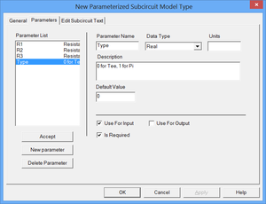
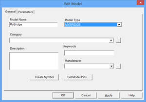
At this point, you will create a new Parameterized Subcircuit Model Definition. Go to the Device Editor's File Menu and select "New Parameterized Subcircuit Model Definition…". A dialog opens up with three tabs as shown above. In the first "General" tab, you enter a name for your parameterized subcircuit model definition, making sure that there are no spaces in the name. In this case, use the same name as your symbol, "MyBridge". You can also assign a category and write a description. Then, switch to the second tab of the dialog, "Parameters". This is where you define the parameters of your device. For each parameter, use the "New Parameter" button to initiate a new parameter. Then, change its name, specify its "Data Type" (e.g. Real) and optional "Units". You can also write a description of your parameter. Make sure the "Use for Input" box is checked. Leaving it unchecked will cause the parameter not to show up in other dialog boxes. The check box labeled "Is Required" is for when you want the Workshop to specifically use this parameter. If you check the box, then you also must enter a "Default Value" for it. Click the "Accept" button once you are finished with the particular parameter. Note that you must click "New Parameter" to enter and edit a new parameter. Not doing so will overwrite the parameter that happens to be highlighted.
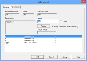
For this lesson, define three real-type parameters "R1", "R2" and "R3" to represent three resistance values with units of "Ohm" and identical default values of 100. Also, define a fourth real-type parameter called "Type" with the default value of 0. If Type = 0, your model will represent a Tee resistive bridge. When Type = 1, your model will switch to a Pi resistive bridge.
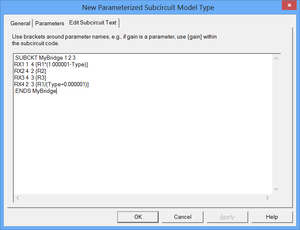
Next, switch to the "Edit Subcircuit Text" tab. Here you will enter the actual subcircuit or Netlist code where you will use your parameters. If you know what you're doing, you can start entering your subcircuit Netlist code, starting with the .SUBCKT statement and ending with the .ENDS statement. Your subcircuit needs to be in Berkeley Spice 3f5 format with XSpice extensions. All user defined parameters must go in between two curly brackets { }. All standard mathematical operations (+,-,/,*), power of (^), and many mathematical functions are supported. For example, the first resistance parameter is used as {R1} and can replace the numeric value for a certain property of some element. The sum of the three resistances is expressed as {R1+R2+R3}.
For this lesson, enter the following Netlist code:
.SUBCKT MyBridge 1 2 3
RX1 1 4 {R1/(1.000001-Type)}
RX2 4 2 {R2}
RX3 4 3 {R3}
RX4 2 3 {R1/(Type+0.000001)}
.ENDS MyBridge
In the above code, when Type = 0 (Tee), RX1 acts as a series resistance R1 and RX4 is almost an open circuit. When Type = 1 (Pi), RX1 is almost a short circuit and RX4 acts as a shunt resistance R1. Once you're satisfied with all your entries, click OK and continue to the next step.
Defining a Simulation Model Using Your New Parameterized Subcircuit Model Definition
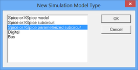
Every device in B2.Spice A/D must have a simulation model, which can be either of a subcircuit type or a process (technology) type. At this point, you will create your new simulation model. Go to the Device Editor's File Menu and select "New Simulation Model…" A small dialog pops up asking for the type of the model. Select the "Spice or XSpice Parameterized Subcircuit" option and click OK. In the Model Dialog, enter the new model's name, "MyBridge" as before. From the "Model Type" drop-down list, select the parameterized subcircuit type that you just created in the previous step. In this case, you will select "MyBridge" for the Model Type. You can skip creating a symbol for your simulation model or setting the model pins.
Click on the "Parameters" tab, and you will see the parameters that you specified earlier. You can change the values of the parameters here if you like. Or you can leave them blank for now and change them later once you have the part in the Schematic Editor. Once you're done editing the simulation model, click OK to accept it.
Creating a New Device Using Your New Simulation Model
The last step is device creation. Go to the Device Editor's File Menu and select "New Device…" The Edit Device Dialog opens up. Enter a name for your new device, e.g. "MyBridge" as before. In the "Simulation Model" section of the dialog, select the model that you created in the previous step. In the "Symbol" section of the dialog, select the three-pin symbol that you created earlier in this tutorial lesson. The figure below shows the Edit Dialog when you first opened it and after filling various fields:
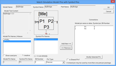
The last task, which happens to be very critical, is to match the model pins with the symbol pins. Recall that you called your symbol pins P1, P2 and P3. However, your model's pins (or terminals or external nodes) were indexed 1, 2 and 3. Now you have to map the model pins onto the symbol pins. To do so, click the large button labeled "Connect Symbol Pins to Model Pins" in the Edit Device Dialog. A new dialog opens up like the one shown below. Click on each model pin in the leftmost table, then click on a symbol pin in the middle box, and make the pairing by clicking on the "Add New ==>" button. If you mess up, you can select the pairing in the right box and click the "<==Remove" button to unmatch the pair. Click OK once you have assigned all the simulation pins. Then, click OK to accept the part.
And that's it! Your new parameterized device have just been added to the Parts Database and is ready for use.
Using Your New Parameterized Part in a New Circuit
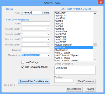
At this point, close the Device Editor. Also, close all instances of B2.Spice A/D application that might be open on your desktop. Open a new project in B2.Spice A/D. To access and place your new parameterized part in the Workshop, you can search the Parts Bin in the "Add Part" tab of the Toolbox as you did in the last tutorial lesson. Another convenient way is to go to the Parts Menu and choose the "Select Part..." item to open the Select Device Dialog a shown in the opposite figure. Type in the name of your part "MyBridge" or use the filters to easily search the database. Once you find it, click the "Select Device" button to place it in your schematic.
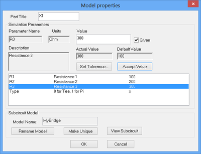
Pull your part up in the Workshop and double-click on it to view and change the values of your custom parameters. The parameters will be evaluated automatically as you run a simulation. Set the values of the parameters R1, R2 and R3 equal to 100, 200 and 300 Ohms, respectively. Leave the default value of parameter "Type" as 0, which corresponds to a Tee network configuration. The figure below shows the property dialog of "MyBridge" when you first open it and after you change the parameter values.
Notice that you can change the subcircuit model of your parameterized part right from it property dialog by clicking the "View Subcircuit" button.
| |
You can change the subcircuit model of a part in your circuit temporarily without saving it permanently to the Parts Database. |
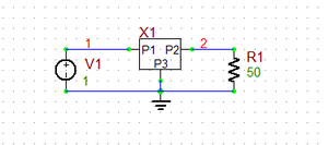
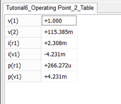
Next, place a 1V DC voltage source in you circuit and connect it to port 1 (P1) of your part. Ground port 2 (P2) and place a 50 Ohm resistive load at port 3 (P3) as shown in the figure below. Run a quick "DC Bias" test of your circuit to view voltages and current at various nodes as shown below.
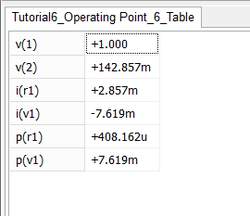
Now, change the configuration of your resistive bridge to a Pi network by opening its property dialog and change the value of the parameter "Type" to 1. Run another DC Bias test of your circuit to view the new voltages and current at various nodes as shown below.
These are obviously different than the previous set of data corresponding to the Tee network as you would have expected.
Verifying Your New Parameterized Subcircuit Model
In order to verify that your Netlist model works correctly, next you will use the Tee-to-Pi network transformation to find an equivalent Pi network for your first Tee configuration in the previous step. The transformations for Tee and Pi networks as defined in the figure shown at the top of this tutorial lesson are given by the following formulas:
[math]Z_{P1} = Z_{T2} + Z_{T3} + \frac{Z_{T3}Z_{T2}}{Z_{T1}}[/math]
[math]Z_{P2} = Z_{T1} + Z_{T2} + \frac{Z_{T1}Z_{T2}}{Z_{T3}}[/math]
[math]Z_{P3} = Z_{T1} + Z_{T3} + \frac{Z_{T3}Z_{T1}}{Z_{T2}}[/math]
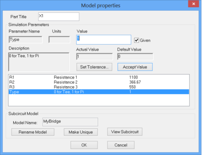
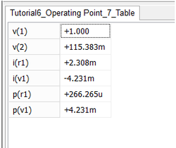
With the Tee impedance values: [math]Z_{T1} = 100, Z_{T2} = 200, Z_{T3} = 300,[/math] you will get Pi impedance values: [math]Z_{P1} = 1100, Z_{P2} = 366.67, Z_{P3} = 550[/math]. Open the property dialog of "MyBridge" one more time and change the values of the parameters R1, R2 and R3, respectively. Keep the value of the parameter "Type" as 1. Run a new DC Bias test of your circuit to view the latest voltages and current at various nodes as shown below. You will find that these are identical to the case of the Tee configuration of the previous step. So your Netlist subcircuit code works fine!


