Difference between revisions of "NeoScan Manual Part A: Getting Started"
(→System Overview) |
|||
| Line 349: | Line 349: | ||
In spite of its sophisticated capabilities, the [[NeoScan]] system is easy to learn and operate. You can start using the system within hours. Below are the procedures to help you get started using [[NeoScan]]. We highly recommend that you complete chapters 2 and 3 of [[NeoScan]] and familiarize yourself with its basic functions before attempting to run the system. Turn the [[NeoScan]] system on at least 30 minutes before any operation for warm-up. Before getting started, consider the following precautions: | In spite of its sophisticated capabilities, the [[NeoScan]] system is easy to learn and operate. You can start using the system within hours. Below are the procedures to help you get started using [[NeoScan]]. We highly recommend that you complete chapters 2 and 3 of [[NeoScan]] and familiarize yourself with its basic functions before attempting to run the system. Turn the [[NeoScan]] system on at least 30 minutes before any operation for warm-up. Before getting started, consider the following precautions: | ||
| − | + | <ul> | |
| − | + | <li> | |
| − | + | The system operates from a 100V or 120V nominal AC power source having a line frequency of 50 or 60 Hz. Before connecting the power cord to a power source, verify that the AC input voltage value is correct. | |
| − | In order to avoid EMC/EMI effect, keep the [[NeoScan]] box as far away from the DUT as possible. | + | </li> |
| + | <li> | ||
| + | [[NeoScan]] real-time field measurement and scanning system contains a 40 mW laser diode emitting Class 3B laser radiation at ~1550 nm. The direct output power from the fiber port of each probe channel on the front panel is less than 10 mW. The beam at 1550 nm is invisible to human being and the invisible beam can be hazardous if directed at the eye. Direct exposure of eye to the invisible laser beam must be avoided. | ||
| + | </li> | ||
| + | <li> | ||
| + | The fans in [[NeoScan]] optical mainframe are required to maintain proper operation. Do not block the vents in the frame box. | ||
| + | </li> | ||
| + | <li> | ||
| + | In order to avoid EMC/EMI effect, keep the [[NeoScan]] box as far away from the DUT as possible. | ||
| + | </li> | ||
| + | <li> | ||
Follow standard electrostatic-discharge precaution, including grounding yourself prior to making cable connections to the system. A ground strap provides the most effective grounding and minimizes the likelihood of electrostatic damage. | Follow standard electrostatic-discharge precaution, including grounding yourself prior to making cable connections to the system. A ground strap provides the most effective grounding and minimizes the likelihood of electrostatic damage. | ||
| + | </li> | ||
| + | <li> | ||
Handle the probes and the PM fibers with extreme care. | Handle the probes and the PM fibers with extreme care. | ||
| + | </li> | ||
| + | <li> | ||
Gently clean and attach the appropriate fiber connectors to the correct fiber port of the [[NeoScan]] system. | Gently clean and attach the appropriate fiber connectors to the correct fiber port of the [[NeoScan]] system. | ||
| + | </li> | ||
| + | <li> | ||
Do not excessively pull or bend the fiber. | Do not excessively pull or bend the fiber. | ||
| + | </li> | ||
| + | <li> | ||
The probe tip is extremely fragile. Do not strike the probe tip. Always keep the probes in a safe place. | The probe tip is extremely fragile. Do not strike the probe tip. Always keep the probes in a safe place. | ||
| + | </li> | ||
| + | <li> | ||
Keep the cables and the fibers handy in safe positions, but out of the way and untangled. | Keep the cables and the fibers handy in safe positions, but out of the way and untangled. | ||
| + | </li> | ||
| + | <li> | ||
Always use an SMA torque wrench when connecting the SMA connectors. | Always use an SMA torque wrench when connecting the SMA connectors. | ||
| + | </li> | ||
| + | <li> | ||
Do not over-torque the microwave SMA connectors. | Do not over-torque the microwave SMA connectors. | ||
| + | </li> | ||
| + | <li> | ||
Do not over-tighten the optical connectors. | Do not over-tighten the optical connectors. | ||
| + | </li> | ||
| + | </ul> | ||
=== Installing the [[NeoScan]] System === | === Installing the [[NeoScan]] System === | ||
| − | [[NeoScan]] optical mainframe is enclosed in a 4U case with dimensions of 24”(H) x 17”(L) x 13” (W) (61cm x 43cm x 33cm). The instrument weighs 60 pounds (27kg) and contains the entire optical system, control systems, and power conditioning circuits required for electric field measurements. It is packaged in foam. Open the cardboard box and remove the layers of foam. Care must be taken to ensure the optical connectors, the SMA connectors, and the USB connectors on the rear panel are not damaged. Remove the fiber port protection caps and keep safe for reuse when repacking the instrument. The instrument box should contain the corresponding power cord, cables and etc. | + | [[Image:neoscanfig_2_1.png|thumb|center|650px|<i><b>Figure 2.1</b>: Installing NeoScan control computer.</i>]] [[NeoScan]] optical mainframe is enclosed in a 4U case with dimensions of 24”(H) x 17”(L) x 13” (W) (61cm x 43cm x 33cm). The instrument weighs 60 pounds (27kg) and contains the entire optical system, control systems, and power conditioning circuits required for electric field measurements. It is packaged in foam. Open the cardboard box and remove the layers of foam. Care must be taken to ensure the optical connectors, the SMA connectors, and the USB connectors on the rear panel are not damaged. Remove the fiber port protection caps and keep safe for reuse when repacking the instrument. The instrument box should contain the corresponding power cord, cables and etc. |
Unpack the control computer (surface) and the computer holder. Attach the computer holder to the [[NeoScan]] front panel with the screws. Pull up the Holder Lock part on the top left. Place the control computer inside the computer holder. Pull down the Holder Lock part and lock it (Figure 2.1) | Unpack the control computer (surface) and the computer holder. Attach the computer holder to the [[NeoScan]] front panel with the screws. Pull up the Holder Lock part on the top left. Place the control computer inside the computer holder. Pull down the Holder Lock part and lock it (Figure 2.1) | ||
| Line 371: | Line 399: | ||
=== Installing [[NeoScan]] Translation Stage === | === Installing [[NeoScan]] Translation Stage === | ||
| − | Unpack the [[NeoScan]] translation stage components. To install (see Appendix A-l): | + | [[Image:neoscanfig_2_2.png|thumb|center|650px|<i><b>Figure 2.2</b>: Installing NeoScan Translation Stage.</i>]] Unpack the [[NeoScan]] translation stage components. To install (see Appendix A-l): |
| + | <ul> | ||
| + | <lo> | ||
Place the Y Linear Translation Stage on a stable flat table, preferably an optical table. | Place the Y Linear Translation Stage on a stable flat table, preferably an optical table. | ||
| − | + | </lo> | |
| + | <lo> | ||
Mount the X Linear Translation Stage on the Y Linear Translation Stage using four screws as shown by red screws in Figure 2.2. | Mount the X Linear Translation Stage on the Y Linear Translation Stage using four screws as shown by red screws in Figure 2.2. | ||
| − | + | </lo> | |
| + | <lo> | ||
Mount the Plate on the X Linear Translation Stage. Fasten its four edges with screws as indicated by green arrows in Figure 2.2. | Mount the Plate on the X Linear Translation Stage. Fasten its four edges with screws as indicated by green arrows in Figure 2.2. | ||
| − | + | </lo> | |
| + | <lo> | ||
Place the X, Y, and Z Miniature Translation Stages on the front edge of the Optical Plate and fasten its four edges with screws as indicated by arrows in Figure 2.2. | Place the X, Y, and Z Miniature Translation Stages on the front edge of the Optical Plate and fasten its four edges with screws as indicated by arrows in Figure 2.2. | ||
| − | + | </lo> | |
| + | <lo> | ||
Attach the Plastic Probe Fixture to the XYZ Miniature Translation Stage. | Attach the Plastic Probe Fixture to the XYZ Miniature Translation Stage. | ||
| + | </lo> | ||
| + | </ul> | ||
=== Unpacking the EO Probes === | === Unpacking the EO Probes === | ||
Revision as of 22:38, 3 March 2017
Contents
- 1 Overview
- 2 NeoScan Probe Installation
- 2.1 Shipping & Handling Precautions
- 2.2 Installing the NeoScan System
- 2.3 Installing NeoScan Translation Stage
- 2.4 Unpacking the EO Probes
- 2.5 Handling the Probes and the Fibers
- 2.6 Connecting the Probe to NeoScan Optical Mainframe
- 2.7 Quick Test of the NeoScan System
- 2.8 Deploying the Probe on a Probe Fixture
Overview
General Overview
NeoScan® real-time field measurement and scanning system is a turnkey, electric or magnetic field probe and measurement system. It can be configured as a near-field scanning system for mapping aperture-level field distributions with minimal invasiveness to the device or system under test. Or it can be used as a real-time field probe system for sensing or detecting electric and magnetic fields in a variety of media.
The NeoScan system can be used as an essential tool for test and evaluation of antennas and phased array systems and is particularly useful for phase characterization and calibration. Unlike conventional near-field scanning systems that utilize metallic radiators to pick up the fields, NeoScan probes are non-metallic, operating based on electro-optic (EO) or magneto-optic (MO) effects. Its field probes feature extremely small EO or MO crystals mounted at the tip of an optical fiber. The combination of the small probe size and absolutely non-metallic parts leads to the ultimate radio frequency (RF) non-invasiveness.
NeoScan provides detailed field maps of passive and active devices and circuits including RFIC’s and MMIC’s. Such invaluable information can effectively be used for design validation, model verification, diagnostics and fault isolation or performance evaluation of various parts of RF systems. It is also an alternative compact range for measurement of far-field radiation patterns of antennas and arrays, dispensing with a costly anechoic chamber. The system can be used in real-time, polarimetric and coherent sensing and probing of wideband signals and pulses, EMC/EMI testing, and medical device measurements and characterization of biological environments. The NeoScan system can be configured in a multi-channel architecture for simultaneous field measurement at multiple points and locations. Different channels can measure different polarizations in a coherent manner.
Features of the NeoScan System
- Wideband operational bandwidth: few MHz to 20GHz, measuring repetitive signals with 50-ps rise time, 10-ns duration, and 80 V/m amplitude with a 10% to 90% definition
- Hardware system sensitivity requirements of 2 V/m/√Hz
- Electric field real-time measurement capability
- Multi-port Integrated FC/APC Input
- Multi-port SMA RF Output
- Scanning measurement capability
- Simultaneous measurement of amplitude and phase
- Scanning area up to 80” x 80” (2 x 2 m)
- 0.1 micron resolution linear encoder
- Integrated Optical Bench:
- 1550 nm Diode Laser (laser beam spot < 100 μm sq)
- Polarization Controller and Analyzer
- AC and DC photodetectors
- Very wide dynamic range (>70 dB) and linear response range in 1 V/m to 2 MV/m
- One normal field probe and two tangential field probe, each having a FC/APC optical fiber connector (Includes 10 m PM fibers on all probes)
- System Operation, Monitoring, and Optimization Software
General Description

A typical EO probe is composed of an optical fiber affixed with an EO crystal coated with a dielectric reflection layer on its bottom surface as shown in Figure 1.2. These probes have very delicate optical interconnects and extreme care must be taken in handling the probes to prevent excessive shock, bending and out of plane stresses.
Due to its broad measurement bandwidth and high spatial resolution, the EO measurement technique is a promising means to characterize RF systems such as microwave and millimeter-wave integrated circuits, HPM sources and systems, and large-scale active arrays and other radiating structures. Unlike the conventional electrical measurement techniques which require some type of metal structure for the resonant detection of an RF signal, NeoScan’s unique real-time EO electric field measurement method requires no metal components. As a result, the field perturbation caused by introducing metal within the vicinity of a device under test (DUT) is significantly reduced.
 |
 |
Figure 1.3 shows the electric and magnetic fields distribution of a traveling RF wave with a normal probe shown in typical orientation. To detect the maximum electric field in this configuration, the propagation direction of the optical beam of the probe should be parallel to the E-field direction. In general, a normal EO probe is only sensitive to the electric field component parallel to the probe handle, whereas a tangential probe is sensitive to the electric field component perpendicular to the probe handle. Yet, the E-field sensitivity of a tangential probe depends on its crystal orientation sitting on its tip.

Due to the fast response of the EO crystal, it is possible to measure extremely high-bandwidth signals with the normal SNR limitations of wideband signal detection. Using this capability, EMAG Technologies Inc. has developed the world’s first fiber-based real-time polarimetric electric field sensor system – NeoScan – for the measurement of high-power microwave signals. Figure 1.4 is an example of a real time measurement of a 6.6 nsec pulse with 10 kV/m peak field strength. The upper trace shown on the oscilloscope is the received signal, and the lower trace is the detected signal.
The NeoScan system is capable of measuring signals with bandwidths up to 20 GHz and signal levels as low as 1 V/m for optical probes with a 10 m PM fiber. Because the optical probes are free of metallic parts, it is possible to measure extremely high-field strengths since there are no free electron surfaces to generate arcing. The NeoScan can measure fields up at least 2 MV/m and possibly higher.
System Overview
The NeoScan real-time field measurement and scanning system consists of:
-
An optical mainframe with a touchscreen control computer that can be used for either real-time high power microwave measurement or E-field scanning as shown in Figure 1.5.
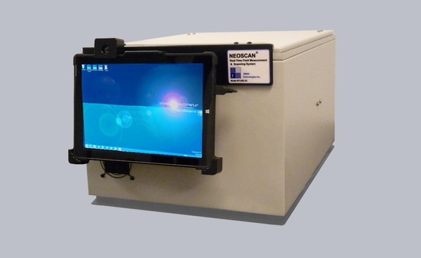 Figure 1.5: The NeoScan Optical Mainframe System.
 Figure 1.6: NeoScan 2-axis translation stage.
The power switch on the back will turn the system and the laser on or off. It is recommended to turn the NeoScan system on at least 30 minutes before any operation for warm-up. A USB port is used to communicate with control computer. The “Signal Out” channels can be used for real-time measurements. The RF signal can be displayed either on a high resolution oscilloscope or a spectrum analyzer. The channels can also be configured for near-field scanning measurement with a U-jumper SMA Cables. The scanning configuration can measure both amplitude and the phase of the signal with a Lock-in Amplifier.
- One normal probe and two tangential probes
- One 2-axis translation stage with a stage controller for scanning operation (Figure 1.6)
- One RF Lock-In Amplifier
- One GPIB-USB cable for instrument control
- One USB multi-port Hub for instrument control
- The NeoScan system control software package


Additional equipment needed to configure NeoScan as a field scanning system include:
- A signal generator to provide the local oscillator (LO) signal for NeoScan’s output mixer
- A signal generator to provide a 100 MHz reference signal to lock-in amplifier
The Front Panel of NeoScan Optical Mainframe
The front panel is the main interface to the system. It contains a control computer that that runs Microsoft Windows, and controls, commands, and monitors the NeoScan system’s status (Figure 1.7).

The Rear Panel of NeoScan Optical Mainframe
The rear panel is the interface to the instruments and provides complete access for external control, optical fiber excitation, and RF signal output (Figure 1.8). It contains:
- A USB interface port for computer control of the system
- The power switch and red LED Power indicator for turning on or off the system
- The AC power cord. The AC power requirement is 110V, 60Hz with a 250V 2A fuse
- Three SMA connector for RF output (Signal Out)
- Three fiber FC/APC connector (Probe)
- SMA connectors for frequency scanning mixer includes: IF Out, LO In, and RF In
- SMA connectors for IF Switch Out and IF Switch Ins
- An electric fan

Acronyms and Abbreviations
|
2D: 2-dimentional
m: meter
|
NeoScan Probe Installation
Shipping & Handling Precautions
The NeoScan system contains extremely sensitive and fragile components. Use extreme caution whenever operating this system. Do not attempt to service or adjust or install substitute parts to its components. Please contact EMAG Technologies Inc. for service and more information.
In spite of its sophisticated capabilities, the NeoScan system is easy to learn and operate. You can start using the system within hours. Below are the procedures to help you get started using NeoScan. We highly recommend that you complete chapters 2 and 3 of NeoScan and familiarize yourself with its basic functions before attempting to run the system. Turn the NeoScan system on at least 30 minutes before any operation for warm-up. Before getting started, consider the following precautions:
- The system operates from a 100V or 120V nominal AC power source having a line frequency of 50 or 60 Hz. Before connecting the power cord to a power source, verify that the AC input voltage value is correct.
- NeoScan real-time field measurement and scanning system contains a 40 mW laser diode emitting Class 3B laser radiation at ~1550 nm. The direct output power from the fiber port of each probe channel on the front panel is less than 10 mW. The beam at 1550 nm is invisible to human being and the invisible beam can be hazardous if directed at the eye. Direct exposure of eye to the invisible laser beam must be avoided.
- The fans in NeoScan optical mainframe are required to maintain proper operation. Do not block the vents in the frame box.
- In order to avoid EMC/EMI effect, keep the NeoScan box as far away from the DUT as possible.
- Follow standard electrostatic-discharge precaution, including grounding yourself prior to making cable connections to the system. A ground strap provides the most effective grounding and minimizes the likelihood of electrostatic damage.
- Handle the probes and the PM fibers with extreme care.
- Gently clean and attach the appropriate fiber connectors to the correct fiber port of the NeoScan system.
- Do not excessively pull or bend the fiber.
- The probe tip is extremely fragile. Do not strike the probe tip. Always keep the probes in a safe place.
- Keep the cables and the fibers handy in safe positions, but out of the way and untangled.
- Always use an SMA torque wrench when connecting the SMA connectors.
- Do not over-torque the microwave SMA connectors.
- Do not over-tighten the optical connectors.
Installing the NeoScan System

Unpack the control computer (surface) and the computer holder. Attach the computer holder to the NeoScan front panel with the screws. Pull up the Holder Lock part on the top left. Place the control computer inside the computer holder. Pull down the Holder Lock part and lock it (Figure 2.1)
Installing NeoScan Translation Stage

-
<lo>
Place the Y Linear Translation Stage on a stable flat table, preferably an optical table.
</lo>
<lo>
Mount the X Linear Translation Stage on the Y Linear Translation Stage using four screws as shown by red screws in Figure 2.2.
</lo>
<lo>
Mount the Plate on the X Linear Translation Stage. Fasten its four edges with screws as indicated by green arrows in Figure 2.2.
</lo>
<lo>
Place the X, Y, and Z Miniature Translation Stages on the front edge of the Optical Plate and fasten its four edges with screws as indicated by arrows in Figure 2.2.
</lo>
<lo>
Attach the Plastic Probe Fixture to the XYZ Miniature Translation Stage.
</lo>
Unpacking the EO Probes
The NeoScan probes are extremely sensitive and fragile components. Use extreme caution whenever operating them. EO probes have been packed in separate boxes (Figure 2.3). The probes are delicate, care must be taken to ensure that the fiber and probe tip are not bent hard or dropped. The probe heads are placed in foam and the probes are housed in a box surrounded by bubble wrap on all sides.
To unpack, open the box top. Remove the visible bubble wrap and remove the entire foam structure from the box. Cut the tape holding the foam structure halves together and remove the top. Remove any bubble wrap in the foam structure. Remove the cardboard covering the probe tip and any small pieces of foam holding the EO Probe down in the foam.
To remove a probe and the fiber from the box:
Carefully press the both sides of the foam near the probe head, carefully un-wedge the probe from its slot, and then lift the probe. Figure 2.4 shows a picture how to remove a probe.
Carefully remove the probe from the foam, making sure to grasp the probe glass tube and not the probe tip, as this may damage the EO probe.
While holding the probe from its glass tube and keep the fiber sheath in your hand, avoid stretching the white plastic shield part of the fiber. Do not pull the plastic shield part hard.
Handling the Probes and the Fibers
The Probes and the fibers are made of a very pure, sensitive, and expensive materials. Treat them with care. Unwind a fiber gently and work out any tangles carefully.
DO NOT pull hard the fiber. DO NOT bend the fiber to a radius smaller than 4” (10 cm). DO NOT strike the probe tip.
Remove the protective cap on the optical fiber cable connector. Connectors should be cleaned before interconnection. Any dirt or contamination can damage the connector or degrade performance. In other words, fiber optic connectors should to be cleaned every time they are mated and unmated. Use a dry cleaning cloth (reel-based cassette cleaner) to remove dirt, dust, and oil from connector end faces (Figure 2.5). You can also carefully clean a dirty fiber connector with isopropyl alcohol (IPA) and then dry with FIS fiber optic cleaner.
Connecting the Probe to NeoScan Optical Mainframe
The probe is coupled with a 10-meter-long PM fiber and connects to the optical mainframe with a FC/APC optical fiber connector. Remove the APC protection caps and keep safe for reuse when repacking the instrument. Gently clean and attach the appropriate fiber connectors to the correct fiber ports of the NeoScan system. There is a pre-aligned (slow or fast axis) adjustable key connectors for the PM axis alignment across a connection. Make sure the key is aligned in the slot properly before tightening, see Figure 2.6.
Quick Test of the NeoScan System
As a quick system test:
Plug in the NeoScan optical mainframe power cord into an electrical receptacle and turn it on. Connect control computer AC power adapter and turn on the control computer. Connect USB multi-port Hub AC power adapter to the power. Connect the NeoScan Optical Mainframe USB Interface Port on the rear panel to a port on the USB Hub, then connect the control computer USB Interface Port to another port on the USB Hub. The USB Hub is a plug and play device. Attach the appropriate fiber connectors to the correct fiber ports of the NeoScan system (Probe 1, Probe 2, or Probe 3), see section 2.6. Open the NeoScan Optical Bench Manager program. The NeoScan Optical Bench Manager program is a Labview-Based System Operation which monitors the system status and the total return and polarization optical powers (see section 3.1 for more details). It is accessible through the desktop or Windows Explorer by double clicking on NeoScanOBM icon as shown in Figure 2.7. The program will start running as shown in Figure 2.8. When the program starts, the system should detect the total return power and polarization power and display their graphs over time and show their numerical values in mW, see Figure 2.8. The green “Probe Detected” indicator light will indicate that the probe is connected to the correct channel. Otherwise, if either the total return power or the polarization power is too low (less than 0.3 mW), the information panel will remind the users to correct the problem. This can be the case if the probe is not connected or is defective or there is a problem with the NeoScan system (Figure 2.9). Select the channel number you want to check using the dropdown list labeled “Select Channel.”
Deploying the Probe on a Probe Fixture
During the scan or optimization process, the probe will be mounted on a plastic probe fixtures. The plastic probe fixtures has been mounted on translation stage by a single cap screw and holds the probe (Figure 2.10). The probe is positioned inside the gap located on probe holder and is secured by a cap which is fastened by screws as shown in Figure 2.11.
Set up the 2-axis translation stage on a stable flat table, an optical table is preferred. Mount the plastic probe fixtures on the Z linear translation stage using the screw, Loosen all screws of the cubic probe holder. Lift the cap and rest the probe holder on a flat horizontal flat surface. Gently insert the probe into the gap in the plastic probe holder in such a way that that about 0.6” (1.5cm) of the probe comes out from the either ends of the gap (Figure 2.11). While the probe is sitting inside the gap, place the cap on the probe holder and secure it by fastening the four plastic screws. Make sure it is tight is enough so that the probe does not slip out of the gap. Yet, do not tighten hard since it may break the probe glass. Tighten the screws until you feel that you are not able to rotate the probe by your fingers. Place the cube holder inside the probe fixture head in such a way that the probe passes through the existing hole (Figure 2.12). Make sure the probe does not hit the edges of the hole, otherwise, it may break and the crystal may fall off. To avoid bending the soft plastic shield of the fiber, pass the fiber through the top of the probe fixture using regular (Scotch) adhesive tapes as shown in Figure 2.13. Important: When pulling out the probe from the hole, make sure the probe is positioned vertically and the probe tip does not touch the edges of the hole.
Two black markers on the tangential probe indicate the E-field sensitivity direction (probes’ polarization direction). They should be oriented along the electric field in order to detect the maximum signal, see Figure 2.14.