Difference between revisions of "Numerical Modeling of Electromagnetic Problems Using EM.Cube"
Kazem Sabet (Talk | contribs) |
Kazem Sabet (Talk | contribs) |
||
| Line 240: | Line 240: | ||
* '''Perfect Electric Conductor (PEC)''': ε<sub>r</sub> = μ<sub>r</sub> = 1, σ = ∞, σ<sub>m</sub> = 0 | * '''Perfect Electric Conductor (PEC)''': ε<sub>r</sub> = μ<sub>r</sub> = 1, σ = ∞, σ<sub>m</sub> = 0 | ||
* '''Perfect Magnetic Conductor (PMC)''': ε<sub>r</sub> = μ<sub>r</sub> = 1, σ = 0, σ<sub>m</sub> = ∞ | * '''Perfect Magnetic Conductor (PMC)''': ε<sub>r</sub> = μ<sub>r</sub> = 1, σ = 0, σ<sub>m</sub> = ∞ | ||
| + | |||
| + | == Variety of Source Types in EM.Cube == | ||
| + | |||
| + | In order to perform an electromagnetic simulation in any of [[EM.Cube]]'s computational modules, you need to excite your physical structure using some kind of source. In most cases, you can define more than one source if necessary. In [[EM.Tempo]], a source pumps energy into your FDTD computational domain in the form of a temporal waveform varying as a function time. In the MoM-based modules, [[EM.Picasso|EM.picasso]] and [[EM.Libera]], a source provides the "right-hand-side (RHS)" vector of the MoM linear system resulting from the integral equation formulation of your boundary value problem. In EM.Illuumina, a source is used to illuminate your surfaces. In [[EM.Terrano]], a source acts as a transmitter that launches the broadcast signal into the free space. In [[EM.Ferma]], you need either an electric or magnetic source to set the boundary conditions for the Laplace equation or provide the source term for the Poisson equation. | ||
| + | |||
| + | In each module, you should choose the right source type depending on the purpose of your simulation and based on the observables you define for your project. For example, for computing the radar cross section (RCS) of a target, you need a plane wave source. If you are interested in computing the S/Z/Y [[parameters]] of your structure, then you have to choose a source type like a gap or lumped source that supports a "Port Definition" observable. | ||
| + | |||
| + | <table> | ||
| + | <tr> | ||
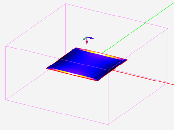
| + | <td> [[Image:Source12.png|thumb|360px|Current distribution on a metallic plate excited by a plane wave source.]] </td> | ||
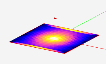
| + | <td> [[Image:Source13.png|thumb|360px|Current distribution on a metallic plate excited by a short horizontal dipole source above it.]] </td> | ||
| + | </tr> | ||
| + | </table> | ||
| + | |||
| + | [[EM.Cube]] provides a large variety of source types listed in the table below: | ||
| + | |||
| + | {| class="wikitable" | ||
| + | |- | ||
| + | ! scope="col"| Source Type | ||
| + | ! scope="col"| Supporting Module(s) | ||
| + | |- | ||
| + | | Lumped Source | ||
| + | | [[EM.Tempo]] | ||
| + | |- | ||
| + | | Waveguide Source | ||
| + | | [[EM.Tempo]] | ||
| + | |- | ||
| + | | Distributed Source | ||
| + | | [[EM.Tempo]] | ||
| + | |- | ||
| + | | Gap Source | ||
| + | | [[EM.Picasso]], [[EM.Libera]] | ||
| + | |- | ||
| + | | Probe Source | ||
| + | | [[EM.Picasso]] | ||
| + | |- | ||
| + | | De-embedded Source | ||
| + | | [[EM.Picasso]] | ||
| + | |- | ||
| + | | Hertzian Dipole Source | ||
| + | | [[EM.Tempo]], [[EM.Illumina]], [[EM.Picasso]], [[EM.Libera]], [[EM.Terrano]] | ||
| + | |- | ||
| + | | Plane Wave Source | ||
| + | | [[EM.Tempo]], [[EM.Illumina]], [[EM.Picasso]], [[EM.Libera]] | ||
| + | |- | ||
| + | | Gaussian Beam Source | ||
| + | | [[EM.Tempo]] | ||
| + | |- | ||
| + | | Huygens Source | ||
| + | | [[EM.Illumina]], [[EM.Picasso]], [[EM.Libera]] | ||
| + | |- | ||
| + | | Transmitter Set | ||
| + | | [[EM.Terrano]] | ||
| + | |- | ||
| + | | Fixed-Potential PEC with Nonzero Voltage | ||
| + | | [[EM.Ferma]] | ||
| + | |- | ||
| + | | Volume Charge Source | ||
| + | | [[EM.Ferma]] | ||
| + | |- | ||
| + | | Wire Current Source | ||
| + | | [[EM.Ferma]] | ||
| + | |- | ||
| + | | Volume Current Source | ||
| + | | [[EM.Ferma]] | ||
| + | |- | ||
| + | | Permanent Magnet with Nonzero Magnetization | ||
| + | | [[EM.Ferma]] | ||
| + | |} | ||
| + | |||
| + | == Variety of Simulation Data in EM.Cube == | ||
| + | |||
| + | In most of [[EM.Cube]]'s computational modules, you have to define one or more observables to generate any output data at the end of a simulation. In other words, no simulation data is generated by itself. [[EM.Cube]] provides a large variety of simulation data and observable types as listed in the table below: | ||
| + | |||
| + | {| class="wikitable" | ||
| + | |- | ||
| + | ! scope="col"| Simulation Data Type | ||
| + | ! scope="col"| Required Observable | ||
| + | ! scope="col"| Supporting Module(s) | ||
| + | |- | ||
| + | | Electric and Magnetic Field Distributions | ||
| + | | Field Sensor | ||
| + | | [[EM.Tempo]], [[EM.Terrano|Em.Terrano]], [[EM.Illumina]], [[EM.Ferma]], [[EM.Picasso]], [[EM.Libera]] | ||
| + | |- | ||
| + | | Electric and Magnetic Current Distributions | ||
| + | | Current Distribution | ||
| + | | [[EM.Illumina]], [[EM.Picasso]], [[EM.Libera]] | ||
| + | |- | ||
| + | | Temporal Fields | ||
| + | | Field Probe | ||
| + | | [[EM.Tempo]] | ||
| + | |- | ||
| + | | Far-Field Radiation Patterns | ||
| + | | Far Fields - Radiation Pattern | ||
| + | | [[EM.Tempo]], [[EM.Terrano|Em.Terrano]], [[EM.Illumina]], [[EM.Picasso]], [[EM.Libera]] | ||
| + | |- | ||
| + | | Radar Cross Section (RCS) | ||
| + | | Far Fields - RCS | ||
| + | | [[EM.Tempo]], [[EM.Illumina]], [[EM.Picasso]], [[EM.Libera]] | ||
| + | |- | ||
| + | | Huygens Surface Data | ||
| + | | Huygens Surface | ||
| + | | [[EM.Tempo]], [[EM.Terrano|Em.Terrano]], [[EM.Illumina]], [[EM.Picasso]], [[EM.Libera]] | ||
| + | |- | ||
| + | | Port Characteristics (S/Z/Y Parameters) | ||
| + | | Port Definition | ||
| + | | [[EM.Tempo]], [[EM.Picasso]], [[EM.Libera]] | ||
| + | |- | ||
| + | | Periodic Reflection and Transmission Coefficients | ||
| + | | No Observables Required | ||
| + | | [[EM.Tempo]], [[EM.Picasso]] | ||
| + | |- | ||
| + | | Temporal Electric and Magnetic Energy | ||
| + | | Domain Energy | ||
| + | | [[EM.Ferma]] | ||
| + | |- | ||
| + | | Static Electric and Magnetic Energy & Ohmic Losses | ||
| + | | Field Integral | ||
| + | | [[EM.Ferma]] | ||
| + | |- | ||
| + | | Voltage and Current | ||
| + | | Field Integrals | ||
| + | | [[EM.Ferma]] | ||
| + | |- | ||
| + | | Electric and Magnetic Flux | ||
| + | | Field Integrals | ||
| + | | [[EM.Ferma]] | ||
| + | |- | ||
| + | | Resistance, Capacitance, Inductance | ||
| + | | Field Integrals | ||
| + | | [[EM.Ferma]] | ||
| + | |- | ||
| + | | Received Power | ||
| + | | Receiver Set | ||
| + | | [[EM.Terrano]] | ||
| + | |- | ||
| + | | Singal-to-Noise Ratio (SNR) | ||
| + | | Receiver Set | ||
| + | | [[EM.Terrano]] | ||
| + | |- | ||
| + | | Channel Path Loss | ||
| + | | Receiver Set | ||
| + | | [[EM.Terrano]] | ||
| + | |} | ||
| + | |||
| + | == EM.Cube Mesh Types == | ||
| + | |||
| + | [[EM.Cube]]'s computational modules use a number of different mesh generation schemes to discretize your physical structure. Even [[CubeCAD]] provides several tools for object discretization. In general, all of [[EM.Cube]]'s mesh generation schemes can be grouped into three categories representing their dimensionality: | ||
| + | |||
| + | # Linear Mesh | ||
| + | # Surface Mesh | ||
| + | # Volume Mesh | ||
| + | |||
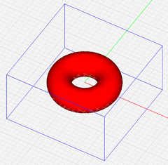
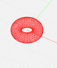
| + | The linear mesh is also known as wireframe mesh and is used by [[EM.Libera]] to discretize the physical structure for Wire MoM simulation. [[EM.Cube]] offer two surface mesh types: triangular surface mesh and hybrid surface mesh. As its name implies, a triangular surface mesh is made up of interconnected triangular cells. [[EM.Terrano]], [[EM.Illumina]], [[EM.Libera]] and [[EM.Picasso]] all use triangular surface mesh generators to discretized surface CAD objects and the surface of solid CAD objects. The hybrid surface mesh is [[EM.Picasso]]'s default mesh. It combines rectangular and triangular cells to discretize planar structures. The hybrid surface mesh generator tries to produce as many identical rectangular cells as possible in rectangular regions of your planar structure. | ||
| + | |||
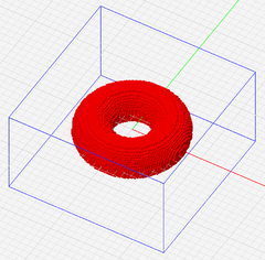
| + | [[EM.Cube]] provides two types of brick meshes to discretize the volume of your computational domain. Brick meshes are entire-domain volume meshes and are made up of cubic cells. Brick meshes are indeed generated by a three-dimensional arrangement of grid lines along the X, Y and Z dimensions. [[EM.Tempo]] offers an Adaptive brick mesh as well as a fixed-cell brick mesh for the FDTD simulation of your physical structure. [[EM.Ferma]] offers only a fixed-mesh brick mesh for the solution of electrostatic and magnetostatic Poisson equations. | ||
| + | |||
| + | <table> | ||
| + | <tr> | ||
| + | <td> [[Image:Mesh1.png|thumb|240px|The geometry of a metallic torus.]] </td> | ||
| + | <td> [[Image:Mesh2.png|thumb|240px|The brick volume mesh of the metallic torus.]] </td> | ||
| + | <td> [[Image:Mesh3.png|thumb|200px|The triangular surface mesh of the metallic torus.]] </td> | ||
| + | </tr> | ||
| + | </table> | ||
| + | |||
| + | == The Significance of Mesh Resolution == | ||
| + | |||
| + | The objects of your physical structure are discretized based on a specified mesh density. The default mesh densities of [[EM.Tempo]], [[EM.Picasso]], [[EM.Libera]] and [[EM.Illumina]] are expressed as the number of cells per effective wavelength. Therefore, the resolution of the default mesh in these modules are frequency-dependent. You can also define the mesh resolution using a fixed cell size or fixed edge length specified in project units. The mesh density of [[EM.Terrano]] is always expressed in terms of cell edge length. The mesh resolution of [[EM.Ferma]] is always specified as the fixed cell size. All of [[EM.Cube]]'s computational modules have default mesh settings that usually work well for most simulations. | ||
| + | |||
| + | The accuracy of the numerical solution of an electromagnet problem depends greatly on the quality and resolution of the generated mesh. As a rule of thumb, a mesh density of about 10-30 cells per effective wavelength usually yields satisfactory results. Yet, for structures with lots of fine geometrical details or for highly resonant structures, higher mesh densities may be required. Also, the particular simulation data that you seek in a project also influence your choice of mesh resolution. For example, far field characteristics like radiation patterns are less sensitive to the mesh density than the near-field distributions on a structure with a highly irregular shape and a rugged boundary. | ||
Revision as of 19:41, 25 July 2016
Contents
- 1 Computational Electromagnetics
- 2 An Overview of EM.Cube's Numerical Solvers
- 3 The Composition of Physical Structure
- 4 Constitutive Parameters of a Material Medium
- 5 Variety of Source Types in EM.Cube
- 6 Variety of Simulation Data in EM.Cube
- 7 EM.Cube Mesh Types
- 8 The Significance of Mesh Resolution
Computational Electromagnetics
Mathematically speaking, all electromagnetic modeling problems require solving some form of Maxwell's equations in conjunction with certain initial and boundary conditions. Radiation and scattering problems are defined over an unbounded domain. Circuit and device problems are often formulated as shielded structures within finite domains. Aside from a few well-known canonical problems, there are no closed-form solutions available for most electromagnetic problems due to the complexity of their domains and boundaries. Numerical analysis, therefore, is the only way to solve such problems.
![]() Click here for a brief review of Maxwell's Equations.
Click here for a brief review of Maxwell's Equations.
Using a numerical method to solve a certain electromagnetic modeling problem typically involves a recurring sequence of steps:
- Geometrical construction of the physical structure and material assignments
- Definition of the computational domain and boundary conditions
- Definition of excitation sources
- Definition of observables
- Geometrical reduction and mesh generation
The above steps reduce your original physical problem to a numerical problem, which must be solved using an appropriate numerical solver. Verifying and benchmarking different techniques in the same simulation environment helps you better strategize, formulate and validate a definitive solution.
A ubiquitous question surfaces very often in electromagnetic modeling: "Does one really need more than one simulation engine? A true challenge of electromagnetic modeling is the right choice of numerical technique for any given problem. Depending on the electrical length scales and physical nature of your problem, some modeling techniques may provide more accurate or computationally more efficient solutions than the others. Full-wave techniques provide the most accurate solution of Maxwell's equations in general. In the case of very large-scale problems, asymptotic methods sometimes offer the only practical solution. On the other hand, static or quasi-static methods may provide more stable solutions for extremely small-scale problems. Having access to multiple simulation engines in a unified modeling environment provides many advantages beyond getting the best solver for your particular problem. Some complex problems involve dissimilar length scales which cannot be compromised in favor of one or another. In such cases, a hybrid simulation using different techniques for different parts of the larger problem can lead to a reasonable solution.
An Overview of EM.Cube's Numerical Solvers
EM.Cube uses a number of computational electromagnetic (CEM) techniques to solve your modeling problems. All of these techniques are based on a fine discretization of your physical structure into a set of elementary cells or elements. A discretized form of Maxwell's equations or some variations of them are then solved numerically over these smaller cells. From the resulting numerical solution, the quantities of interest are derived and computed.
The numerical techniques used by EM.Cube are:
- Finite Different Time Domain (FDTD) method
- Shoot-and-Bounce-Rays (SBR) method
- Physical Optics (PO) method: Geometrical Optics - Physical Optics (GO-PO) method and Iterative Physical Optics (IPO) emthod
- Mixed Potential Integral Equation (MPIE) method for multilayer planar structures
- Wire Method of Moments (WMOM) based on Pocklington integral equation
- Surface Method of Moments (SMOM) with Adaptive Integration Equation (AIM) accelerator
- Finite Difference (FD) method solution of electrostatic and magnetostatic Laplace/Poisson equations
| Module Name | Simulation Engine(s) | Solver Type | Modeling Accuracy | Frequency Range | Fundamental Solution |
|---|---|---|---|---|---|
| EM.Tempo | FDTD | Volumetric solver | Full-wave | Ultra-wideband time-domain | Electric and magnetic fields in the entire domain |
| EM.Terrano | SBR | Ray tracer | Asymptotic | High-frequency harmonic | Electric field ray tubes and power received at receiver locations |
| EM.Illumina | GO-PO & IPO | Surface solver | Asymptotic | High-frequency harmonic | Electric and magnetic currents on surfaces |
| EM.Ferma | FD | Volumetric solver | Static or quasi-static | DC or low-frequency | Electric or magnetic fields in the entire domain |
| EM.Picasso | MPIE | Planar solver | Full-wave | Arbitrary harmonic | Electric and magnetic currents on traces |
| EM.Libera | WMOM & SMOM | Surface & wire solvers | Full-wave | Arbitrary harmonic | Electric and magnetic currents on surfaces or wires |
| Module Name | Material Capability | Excitation/Sources | Lumped Devices |
|---|---|---|---|
| EM.Tempo | PEC, PMC, dielectric, anisotropic, dispersive, complex materials | Lumped and distributed sources, plane wave, Gaussian beam, arbitrary waveform | Passive and active, linear and nonlinear devices and circuits |
| EM.Terrano | Material surfaces, thin walls and material volumes | Transmitters, Hertzian dipoles | N/A |
| EM.Illumina | PEC, PMC, impedance surfaces | Hertzian dipole, plane wave, Huygens source | N/A |
| EM.Ferma | PEC, dielectric or magnetic materials | Charge, current and permanent magnet | N/A |
| EM.Picasso | PEC and slot traces, short vias, infinite substrate layers | Gap source, wave port, Hertzian dipole, plane wave, Huygens source | Simple passive RLC lumped elements |
| EM.Libera | PEC, homogeneous dielectric | Gap source, Hertzian dipole, plane wave, Huygens source | Simple passive RLC lumped elements |
| Module Name | Observables | Applications |
|---|---|---|
| EM.Tempo | Near-field, far-field, RCS, periodic R/T, S/Z/Y parameters, port current/voltage/power | General-purpose field simulator capable of handling complex geometrical and material variations |
| EM.Terrano | Far-field & received power | Radio wave propagation in very large scenes |
| EM.Illumina | Far-field & RCS | Scattering from very large surface structures & antenna-platform combinations |
| EM.Ferma | Electric or magnetic field & potential, voltage, current, energy, power | Small-scale devices and structures |
| EM.Picasso | Current distribution, far-field, periodic R/T, S/Z/Y parameters | Multilayer planar circuits, antennas & arrays, FSS, homogeneous substrates |
| EM.Libera | Current distribution, far-field, RCS, S/Z/Y parameters | Radiation and scattering problems involving metals and homogeneous dielectric materials |
The Composition of Physical Structure
Your Physical Structure in EM.Cube consists of a number of CAD objects you draw in the project workspace. In all EM.Cube modules, you use CubeCAD's common drawing tools and/or its import capability to construct your geometrical structure. In order to perform an electromagnetic simulation, you need to assign material properties to all of your CAD objects in the project workspace. The drawn CAD objects are organized together based on their common properties under one or more object groups or nodes in the Navigation Tree. The grouping of CAD objects is essentially based on their material composition and their associated boundary conditions.
Among EM.Cube's computational modules, EM.Tempo is the most comprehensive in view of material variety offering. EM.Ferma and EM.Libera offer PEC and dielectric material groups similar to EM.Tempo. EM.Illumina offers PEC, PMC and impedance surfaces. EM.Terrano groups objects into material block types that are characterized by their ray interaction properties. EM.Picasso groups objects based on their trace location (i.e. Z-coordinate) in the substrate layer hierarchy.
From an electromagnetic analysis point of view, materials are categorized by the constitutive relations or boundary conditions that relate electric and magnetic fields. EM.Cube offers a large variety of material types listed in the table below:
| Material Type | Supporting Module(s) |
|---|---|
| Perfect Electric Conductor (PEC) | EM.Tempo, EM.Illumina, EM.Ferma, EM.Picasso, EM.Libera |
| Perfect Magnetic Conductor (PMC) | EM.Tempo, EM.Illumina, EM.Picasso |
| Dielectric | EM.Tempo, EM.Ferma, EM.Picasso, EM.Libera, EM.Terrano |
| Impedance Surface | EM.Illumina |
| Conductive Sheet | EM.Picasso |
| Anisotropic Material | EM.Tempo |
| Dispersive Material | EM.Tempo |
| Inhomogeneous Material | EM.Tempo |
| Thin Wire | EM.Tempo, EM.Libera |
Constitutive Parameters of a Material Medium
In general, an isotropic material medium is macroscopically characterized by four constitutive parameters:
- Permittivity (ε) having units of F/m
- Permeability (μ) having units of H/m
- Electric conductivity (σ) having units of S/m
- Magnetic conductivity (σm) having units of Ω/m
The permittivity and permeability of a material are typically related to the permittivity and permeability of the free space as follows:
- [math] \epsilon = \epsilon_r \epsilon_0 [/math]
- [math] \mu = \mu_r \mu_0, \quad \quad [/math]
where ε0 = 8.854e-12 F/m, μr = 1.257e-6 H/m, and εr and μr are called relative permittivity and permeability of the material, respectively.
The constitutive parameters relate the field quantities in the material medium:
- [math] \mathbf{D} = \epsilon \mathbf{E}, \quad \quad \mathbf{J} = \sigma \mathbf{E} [/math]
- [math] \mathbf{B} = \epsilon \mathbf{H}, \quad \quad \mathbf{M} = \sigma_m \mathbf{H} [/math]
where E and H are the electric and magnetic fields, respectively, D is the electric flux density, also known as the electric displacement vector, B is the magnetic flux density, also known as the magnetic induction vector, and J and M are the electric and magnetic current densities, respectively.
The electric conductivity and magnetic conductivity parameters represent the material losses. In frequency-domain simulations under a time-harmonic (ejωt) field assumption, it is often convenient to define a complex relative permittivity and a complex relative permeability in the following manner:
- [math] \epsilon_r = \epsilon^{\prime}_r -j\epsilon^{\prime\prime}_r = \epsilon^{\prime}_r -j\frac{\sigma}{\omega \epsilon_0} [/math]
- [math] \mu_r = \mu^{\prime}_r -j\mu^{\prime\prime}_r = \mu^{\prime}_r - j\frac{\sigma_m}{\omega \mu_0}[/math]
where ω = 2πf, and f is the operational frequency. It is also customary to define electric and magnetic loss tangents as follows:
- [math] \tan \delta = \epsilon^{\prime\prime}_r / \epsilon^{\prime}_r [/math]
- [math] \tan \delta_m = \mu^{\prime\prime}_r / \mu^{\prime}_r [/math]
Three special media frequently encountered in electromagnetic problems are:
- Vacuum or Free Space: εr = μr = 1 and σ = σm = 0
- Perfect Electric Conductor (PEC): εr = μr = 1, σ = ∞, σm = 0
- Perfect Magnetic Conductor (PMC): εr = μr = 1, σ = 0, σm = ∞
Variety of Source Types in EM.Cube
In order to perform an electromagnetic simulation in any of EM.Cube's computational modules, you need to excite your physical structure using some kind of source. In most cases, you can define more than one source if necessary. In EM.Tempo, a source pumps energy into your FDTD computational domain in the form of a temporal waveform varying as a function time. In the MoM-based modules, EM.picasso and EM.Libera, a source provides the "right-hand-side (RHS)" vector of the MoM linear system resulting from the integral equation formulation of your boundary value problem. In EM.Illuumina, a source is used to illuminate your surfaces. In EM.Terrano, a source acts as a transmitter that launches the broadcast signal into the free space. In EM.Ferma, you need either an electric or magnetic source to set the boundary conditions for the Laplace equation or provide the source term for the Poisson equation.
In each module, you should choose the right source type depending on the purpose of your simulation and based on the observables you define for your project. For example, for computing the radar cross section (RCS) of a target, you need a plane wave source. If you are interested in computing the S/Z/Y parameters of your structure, then you have to choose a source type like a gap or lumped source that supports a "Port Definition" observable.
EM.Cube provides a large variety of source types listed in the table below:
| Source Type | Supporting Module(s) |
|---|---|
| Lumped Source | EM.Tempo |
| Waveguide Source | EM.Tempo |
| Distributed Source | EM.Tempo |
| Gap Source | EM.Picasso, EM.Libera |
| Probe Source | EM.Picasso |
| De-embedded Source | EM.Picasso |
| Hertzian Dipole Source | EM.Tempo, EM.Illumina, EM.Picasso, EM.Libera, EM.Terrano |
| Plane Wave Source | EM.Tempo, EM.Illumina, EM.Picasso, EM.Libera |
| Gaussian Beam Source | EM.Tempo |
| Huygens Source | EM.Illumina, EM.Picasso, EM.Libera |
| Transmitter Set | EM.Terrano |
| Fixed-Potential PEC with Nonzero Voltage | EM.Ferma |
| Volume Charge Source | EM.Ferma |
| Wire Current Source | EM.Ferma |
| Volume Current Source | EM.Ferma |
| Permanent Magnet with Nonzero Magnetization | EM.Ferma |
Variety of Simulation Data in EM.Cube
In most of EM.Cube's computational modules, you have to define one or more observables to generate any output data at the end of a simulation. In other words, no simulation data is generated by itself. EM.Cube provides a large variety of simulation data and observable types as listed in the table below:
| Simulation Data Type | Required Observable | Supporting Module(s) |
|---|---|---|
| Electric and Magnetic Field Distributions | Field Sensor | EM.Tempo, Em.Terrano, EM.Illumina, EM.Ferma, EM.Picasso, EM.Libera |
| Electric and Magnetic Current Distributions | Current Distribution | EM.Illumina, EM.Picasso, EM.Libera |
| Temporal Fields | Field Probe | EM.Tempo |
| Far-Field Radiation Patterns | Far Fields - Radiation Pattern | EM.Tempo, Em.Terrano, EM.Illumina, EM.Picasso, EM.Libera |
| Radar Cross Section (RCS) | Far Fields - RCS | EM.Tempo, EM.Illumina, EM.Picasso, EM.Libera |
| Huygens Surface Data | Huygens Surface | EM.Tempo, Em.Terrano, EM.Illumina, EM.Picasso, EM.Libera |
| Port Characteristics (S/Z/Y Parameters) | Port Definition | EM.Tempo, EM.Picasso, EM.Libera |
| Periodic Reflection and Transmission Coefficients | No Observables Required | EM.Tempo, EM.Picasso |
| Temporal Electric and Magnetic Energy | Domain Energy | EM.Ferma |
| Static Electric and Magnetic Energy & Ohmic Losses | Field Integral | EM.Ferma |
| Voltage and Current | Field Integrals | EM.Ferma |
| Electric and Magnetic Flux | Field Integrals | EM.Ferma |
| Resistance, Capacitance, Inductance | Field Integrals | EM.Ferma |
| Received Power | Receiver Set | EM.Terrano |
| Singal-to-Noise Ratio (SNR) | Receiver Set | EM.Terrano |
| Channel Path Loss | Receiver Set | EM.Terrano |
EM.Cube Mesh Types
EM.Cube's computational modules use a number of different mesh generation schemes to discretize your physical structure. Even CubeCAD provides several tools for object discretization. In general, all of EM.Cube's mesh generation schemes can be grouped into three categories representing their dimensionality:
- Linear Mesh
- Surface Mesh
- Volume Mesh
The linear mesh is also known as wireframe mesh and is used by EM.Libera to discretize the physical structure for Wire MoM simulation. EM.Cube offer two surface mesh types: triangular surface mesh and hybrid surface mesh. As its name implies, a triangular surface mesh is made up of interconnected triangular cells. EM.Terrano, EM.Illumina, EM.Libera and EM.Picasso all use triangular surface mesh generators to discretized surface CAD objects and the surface of solid CAD objects. The hybrid surface mesh is EM.Picasso's default mesh. It combines rectangular and triangular cells to discretize planar structures. The hybrid surface mesh generator tries to produce as many identical rectangular cells as possible in rectangular regions of your planar structure.
EM.Cube provides two types of brick meshes to discretize the volume of your computational domain. Brick meshes are entire-domain volume meshes and are made up of cubic cells. Brick meshes are indeed generated by a three-dimensional arrangement of grid lines along the X, Y and Z dimensions. EM.Tempo offers an Adaptive brick mesh as well as a fixed-cell brick mesh for the FDTD simulation of your physical structure. EM.Ferma offers only a fixed-mesh brick mesh for the solution of electrostatic and magnetostatic Poisson equations.
The Significance of Mesh Resolution
The objects of your physical structure are discretized based on a specified mesh density. The default mesh densities of EM.Tempo, EM.Picasso, EM.Libera and EM.Illumina are expressed as the number of cells per effective wavelength. Therefore, the resolution of the default mesh in these modules are frequency-dependent. You can also define the mesh resolution using a fixed cell size or fixed edge length specified in project units. The mesh density of EM.Terrano is always expressed in terms of cell edge length. The mesh resolution of EM.Ferma is always specified as the fixed cell size. All of EM.Cube's computational modules have default mesh settings that usually work well for most simulations.
The accuracy of the numerical solution of an electromagnet problem depends greatly on the quality and resolution of the generated mesh. As a rule of thumb, a mesh density of about 10-30 cells per effective wavelength usually yields satisfactory results. Yet, for structures with lots of fine geometrical details or for highly resonant structures, higher mesh densities may be required. Also, the particular simulation data that you seek in a project also influence your choice of mesh resolution. For example, far field characteristics like radiation patterns are less sensitive to the mesh density than the near-field distributions on a structure with a highly irregular shape and a rugged boundary.
