Difference between revisions of "Digital Tutorial Lesson 1: Examining Logic Gates"
Kazem Sabet (Talk | contribs) |
Kazem Sabet (Talk | contribs) (→Placing Digital Parts) |
||
| Line 44: | Line 44: | ||
| Generic Inverter Gate | | Generic Inverter Gate | ||
| Defaults | | Defaults | ||
| − | |||
| − | |||
| − | |||
| − | |||
| − | |||
| − | |||
| − | |||
| − | |||
| − | |||
| − | |||
| − | |||
| − | |||
| − | |||
|} | |} | ||
| Line 73: | Line 60: | ||
</tr> | </tr> | ||
</table> | </table> | ||
| − | |||
Your circuit at this point should like the figure below: | Your circuit at this point should like the figure below: | ||
| − | + | ||
| − | + | <table> | |
| − | + | <tr> | |
| − | [[File:b2TUT4_5.png| | + | <td> [[File:b2TUT4_5.png|thumb|450px|The digital parts placed in the Schematic Editor.]] </td> |
| − | + | </tr> | |
| − | + | ||
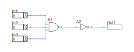
Finally, use one the wiring methods you learned in the earlier tutorial lessons to connect all the parts and I/O ports. At the end, you should have a digital circuit similar to the figure shown at the beginning of this lesson. Straight wires can always be drawn by simply clicking on device pins and dragging a line out of the pins. For drawing bent lines and multi-segment lines, sometimes you have to use the '''Wire Tool'''. | Finally, use one the wiring methods you learned in the earlier tutorial lessons to connect all the parts and I/O ports. At the end, you should have a digital circuit similar to the figure shown at the beginning of this lesson. Straight wires can always be drawn by simply clicking on device pins and dragging a line out of the pins. For drawing bent lines and multi-segment lines, sometimes you have to use the '''Wire Tool'''. | ||
| + | |||
| + | <table> | ||
| + | <tr> | ||
| + | <td> [[File:b2TUT4_1.png|thumb|450px|The finished digital circuit.]] </td> | ||
| + | </tr> | ||
== Testing the Digital Circuit by Stepping Manually == | == Testing the Digital Circuit by Stepping Manually == | ||
Revision as of 23:43, 21 September 2015
Contents
What You Will Learn
In this tutorial you will use generic inverter gates and two-input NAND gates to build two-input and three-input AND circuits. You will learn how to define digital inputs and outputs and use RF.Spice's live digital timing diagrams. It is assumed that by this time you have already completed the first few analog tutorial lessons and are comfortable with navigating the RF.Spice A/D Workshop.
Placing Digital Parts
To build your first digital circuit, you need the following parts:
| Part Name | Part Type | Part Value |
|---|---|---|
| In1 | Digital Input | 1-bit |
| In2 | Digital Input | 1-bit |
| Out1 | Digital Output | 1-bit |
| A1 | Generic NAND Gate | Defaults |
| A2 | Generic Inverter Gate | Defaults |
| |
Unlike analog and mixed-mode circuits that are excited using voltage or current sources, digital circuits require "Digital Input Ports" which can only take either binary or hexadecimal data. |
| |
In analog and mixed-mode circuits, you measure node voltages and device currents. In digital circuits, you probe only binary or hexadecimal data at "Digital Output Ports". |
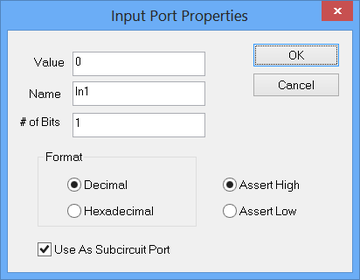
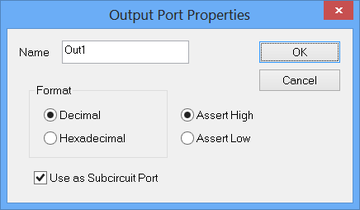
Digital input and output ports are generic and virtual parts. You can get them from the "Digital I/O" submenu of the "Parts Menu". Or you can easily place them in your circuit by typing the keyboard shortcut N for Digital Input and the keyboard shortcut O for Digital Output. Similar to all other parts or devices, digital input and output ports have property dialogs that can be accessed by double-clicking on them. By default, the digital input and output takes 1-bit binary data in decimal format (rather then hexadecimal). The keyboard shortcut for the NAND gate is Alt+A, and keyboard shortcut for the inverter gate is Alt+O.
| |
You can use the keyboard's Space bar to "Repeat Place Device". |
Your circuit at this point should like the figure below:
Set the "Time Step" to 20n, leave the "Walk Factor" at the default value of 2 and close the dialog. Now start the digital simulation by "Stepping" your digital circuit. Click the "Step" ![]() button of the Main Toolbar or select "Step" from the "Simulate Menu" or simply use the keyboard shortcut "Ctrl+H". The simulation time will increase to 20ns, and the output’s value will change to 0. Note that all your three input have initial values of 0. The state of your circuit is shown in the figure below on the left. Next, change the value of Input 1 to 1 and leave the Input 2 and Input 3 at 0. During a live simulation, you can change the values of inputs by clicking on their "Up" and "Down" arrow buttons at their right end. Note that by changing the input values, the output doesn't change immediately. This is because you the engine is waiting for you to step the time to compute the next state of the circuit. Click the "Step"
button of the Main Toolbar or select "Step" from the "Simulate Menu" or simply use the keyboard shortcut "Ctrl+H". The simulation time will increase to 20ns, and the output’s value will change to 0. Note that all your three input have initial values of 0. The state of your circuit is shown in the figure below on the left. Next, change the value of Input 1 to 1 and leave the Input 2 and Input 3 at 0. During a live simulation, you can change the values of inputs by clicking on their "Up" and "Down" arrow buttons at their right end. Note that by changing the input values, the output doesn't change immediately. This is because you the engine is waiting for you to step the time to compute the next state of the circuit. Click the "Step" ![]() button or type "Ctrl+H" one more time. The simulation time increases to 40ns, but the output’s value stays at 0. This is expected as a three-input AND circuit requires all three inputs to be 1 to have an output of 1. The state of the circuit at t = 40s is shown below in the middle figure. Finally, change the values of Input 2 and Input 3 to 1. Step the simulation to 60ns. This time, the output changes to 1 as shown below in the figure on the right.
button or type "Ctrl+H" one more time. The simulation time increases to 40ns, but the output’s value stays at 0. This is expected as a three-input AND circuit requires all three inputs to be 1 to have an output of 1. The state of the circuit at t = 40s is shown below in the middle figure. Finally, change the values of Input 2 and Input 3 to 1. Step the simulation to 60ns. This time, the output changes to 1 as shown below in the figure on the right.
Note that at each time step, the state of all the wire including the output of the NAND gate is displayed on the circuit.
Using Live Digital Timing Diagrams
B2.Spice A/D allows you to view the state of your digital inputs and outputs graphically in real time using "Live Timing Diagrams". The timing diagrams appear at the bottom of the Workshop just like a regular graph. However, these are interactive "live" graphs that change and expand with every time step. For this part of the lesson, you keep the value of "Time Step" at 20ns. First, reset your simulation engine by clicking the "Stop/Reset" ![]() button of the Main Toolbar, or using the keyboard shortcut "Ctrl+E". Also reset the values of all the three inputs to 0.
button of the Main Toolbar, or using the keyboard shortcut "Ctrl+E". Also reset the values of all the three inputs to 0.
To activate the timing diagrams, click the "Show/Hide Live Digital Timing Diagrams" ![]() button of the Schematic Toolbar. Nothing happens immediately because you haven't started a digital simulation yet. Here is the game plan that you will follow next. You will set the values of each input to 1 sequentially, one at a time. You will increment three time steps between any two actions or events. Then, you will revert the values of the three inputs back to 0 sequentially, one at a time, in the reverse order, until all the three inputs are 0 again. The following table shows the timing of the events:
button of the Schematic Toolbar. Nothing happens immediately because you haven't started a digital simulation yet. Here is the game plan that you will follow next. You will set the values of each input to 1 sequentially, one at a time. You will increment three time steps between any two actions or events. Then, you will revert the values of the three inputs back to 0 sequentially, one at a time, in the reverse order, until all the three inputs are 0 again. The following table shows the timing of the events:
| Time | Input 1 | Input 2 | Input 3 |
|---|---|---|---|
| 0ns | 0 | 0 | 0 |
| 60ns | 1 | 0 | 0 |
| 120ns | 1 | 1 | 0 |
| 180ns | 1 | 1 | 1 |
| 240ns | 1 | 1 | 0 |
| 300ns | 1 | 0 | 0 |
| 360ns | 0 | 0 | 0 |
Start the digital simulation with all zero inputs and increment three time steps to 60ns. You will see that four timing diagrams appear at the bottom of the Workshop, one for each input and one for the output. In general every input and output port will have a timing diagram. Then, change the value of Input 1 to 1. Step again and you will see that the timing diagrams immediately get updated because the input states have now changed. Increment two more time steps to 120ns. Then, change the value of Input 2 to 1. Follow this recipe according to the above event table with 60ns intervals until all inputs are set to 0 again. The timing diagrams get updated after each change of state and the final diagrams are shown in the figure above. With a closer look at the output timing diagram, you will be able to see the propagation delay between the input and output ports. For example, at t = 180ns, when all three inputs are 1, you would expect to see the output to jump at 1. However, it take about 20ns for this to happen (at t = 200ns). To understand this, double-click on the NAND gate to open up its property dialog as shown above. You will see that 74LS10D has a "Low-to-High Propagation Delay" of 9ns and a "High-to-Low Propagation Delay" of 10ns. The 74LS04D Inverter has similar propagation delays. When Input 3 jumps to 1 at t = 180ns, it takes the NAND gate a propagation delay of 10ns to fall from its 1 state down to 0. Similarly, it takes the Inverter gate an additional propagation delay of 9ns to rise from its 0 state up to 1. This makes a total delay of 19ns as you can see from the graph.
| |
The timing diagram updates only when there is a change of states of the inputs. |


