Difference between revisions of "EM.Ferma"
Kazem Sabet (Talk | contribs) (→Running Static Simulations in EM.Ferma) |
Kazem Sabet (Talk | contribs) |
||
| Line 69: | Line 69: | ||
In [[EM.Cube]]'s other modules, material types are specified under the "Physical Structure" section of the Navigation Tree, and sources are organized under a separate "Sources" section. In those modules, the physical structure and its various material types typically represent all the CAD objects you draw in your project. Sources are virtual entities that might be associated with certain physical objects and provide the excitation of your boundary value problem. | In [[EM.Cube]]'s other modules, material types are specified under the "Physical Structure" section of the Navigation Tree, and sources are organized under a separate "Sources" section. In those modules, the physical structure and its various material types typically represent all the CAD objects you draw in your project. Sources are virtual entities that might be associated with certain physical objects and provide the excitation of your boundary value problem. | ||
| − | |||
In [[EM.Cube]]'s Static Module, materials and sources are all listed under the "Physical Structure" section of the Navigation Tree, and there is no separate "Sources" section. For example, you can define default zero-potential perfect electric conductors (PEC) in your project to model metal objects. You can also define fixed-potential PEC objects with a nonzero voltage, which can effectively act as a voltage source for your boundary value problem. In this case, you will solve the Lapalce equation subject to the specified nonzero potential boundary values. Both types of PEC objects are defined from the same PEC node of the Navigation Tree by assigning different voltage values. Charge and current sources are defined as CAD objects that you must draw in the project workspace. | In [[EM.Cube]]'s Static Module, materials and sources are all listed under the "Physical Structure" section of the Navigation Tree, and there is no separate "Sources" section. For example, you can define default zero-potential perfect electric conductors (PEC) in your project to model metal objects. You can also define fixed-potential PEC objects with a nonzero voltage, which can effectively act as a voltage source for your boundary value problem. In this case, you will solve the Lapalce equation subject to the specified nonzero potential boundary values. Both types of PEC objects are defined from the same PEC node of the Navigation Tree by assigning different voltage values. Charge and current sources are defined as CAD objects that you must draw in the project workspace. | ||
| − | |||
=== Fixed-Potential PEC Objects=== | === Fixed-Potential PEC Objects=== | ||
| Line 81: | Line 79: | ||
{{Note| You can define any solid or surface object as a fixed-potential PEC object.}} | {{Note| You can define any solid or surface object as a fixed-potential PEC object.}} | ||
| − | |||
=== Dielectric/Magnetic Materials === | === Dielectric/Magnetic Materials === | ||
| Line 90: | Line 87: | ||
{{Note| You can define any solid object as a dielectric or magnetic material object.}} | {{Note| You can define any solid object as a dielectric or magnetic material object.}} | ||
| − | |||
=== Volume Charge Sources === | === Volume Charge Sources === | ||
| Line 96: | Line 92: | ||
You can define volume charge sources with a specified charge density in C/m<sup>3</sup> confined to certain region of your project. You use [[EM.Cube]]'s [[Solid Objects|solid objects]] to define volume charge sources. All the charge sources belonging to the same group have the same color and same charge density value. The charge density can be positive or negative. | You can define volume charge sources with a specified charge density in C/m<sup>3</sup> confined to certain region of your project. You use [[EM.Cube]]'s [[Solid Objects|solid objects]] to define volume charge sources. All the charge sources belonging to the same group have the same color and same charge density value. The charge density can be positive or negative. | ||
To add a new charge source group to a project, right-click on "Volume Charges" on the Navigation Tree, and select "Insert New Charge Source..." From the Charge Source Dialog, you can change the default purple color of the source group or set the values of the Charge Density. | To add a new charge source group to a project, right-click on "Volume Charges" on the Navigation Tree, and select "Insert New Charge Source..." From the Charge Source Dialog, you can change the default purple color of the source group or set the values of the Charge Density. | ||
| − | |||
=== Volume Current Sources === | === Volume Current Sources === | ||
| Line 103: | Line 98: | ||
To add a new volume current source group to a project, right-click on "Volume Currents" on the Navigation Tree, and select "Insert New Current Source..." From the Volume Current Source Dialog, you can change the default brown color of the source group or set the values of the Current Density magnitude and unit direction vector components. The default direction vector is z-directed. | To add a new volume current source group to a project, right-click on "Volume Currents" on the Navigation Tree, and select "Insert New Current Source..." From the Volume Current Source Dialog, you can change the default brown color of the source group or set the values of the Current Density magnitude and unit direction vector components. The default direction vector is z-directed. | ||
| − | |||
=== Wire Current Sources === | === Wire Current Sources === | ||
| Line 112: | Line 106: | ||
{{Note| If you draw [[[Curve Objects]]] under a wire current group, they will be permanently converted to polyline objects before running the simulation engine.}} | {{Note| If you draw [[[Curve Objects]]] under a wire current group, they will be permanently converted to polyline objects before running the simulation engine.}} | ||
| − | |||
=== Permanent Magnets=== | === Permanent Magnets=== | ||
| Line 184: | Line 177: | ||
In EM.Ferma you don't have to select any specific simulation engine. The program looks at the types sources and material objects present in your project workspace and then it determines whether an electrostatic analysis or a magnetostatic analysis or possibly both should be performed. When there are only electric sources present, you will get nonzero electric fields and zero magnetic fields. When there are only magnetic sources present, you will get nonzero magnetic fields and zero electric fields. | In EM.Ferma you don't have to select any specific simulation engine. The program looks at the types sources and material objects present in your project workspace and then it determines whether an electrostatic analysis or a magnetostatic analysis or possibly both should be performed. When there are only electric sources present, you will get nonzero electric fields and zero magnetic fields. When there are only magnetic sources present, you will get nonzero magnetic fields and zero electric fields. | ||
| − | |||
=== Simulation Modes === | === Simulation Modes === | ||
| Line 191: | Line 183: | ||
In a "Parametric Sweep", one ore more [[variables]] are varied at the specified steps(s). This means that you must first define one or more [[variables]] in your projects. [[Variables]] can be associated with CAD object properties like dimensions, coordinates, rotation angles, etc. or with material properties or source properties. For each single variable sample or each combination of variable samples, first all the associated CAD object properties, material properties or source properties are updated in the project workspace. Then is a finite difference solution of your updated static structure is computed and parametric sweep proceeds to the next variable sample or combination. | In a "Parametric Sweep", one ore more [[variables]] are varied at the specified steps(s). This means that you must first define one or more [[variables]] in your projects. [[Variables]] can be associated with CAD object properties like dimensions, coordinates, rotation angles, etc. or with material properties or source properties. For each single variable sample or each combination of variable samples, first all the associated CAD object properties, material properties or source properties are updated in the project workspace. Then is a finite difference solution of your updated static structure is computed and parametric sweep proceeds to the next variable sample or combination. | ||
| − | |||
===Static Simulation Engine Settings=== | ===Static Simulation Engine Settings=== | ||
| Line 198: | Line 189: | ||
{{Note|The value of convergence error affect the accuracy of your simulation results. For most practical scenarios, the default values are adequate. You can reduce the convergence error for better accuracy at the expense of longer computation time.}} | {{Note|The value of convergence error affect the accuracy of your simulation results. For most practical scenarios, the default values are adequate. You can reduce the convergence error for better accuracy at the expense of longer computation time.}} | ||
| − | |||
=== Observables in EM.Ferma === | === Observables in EM.Ferma === | ||
| Line 280: | Line 270: | ||
| − | |||
| − | + | == 2D Quasi-Static Solution of Transmission Lines == | |
| − | + | ||
| − | == 2D Solution | + | |
[[Image:qstatic.png|thumb|300px|Setting up a Transmission Line simulation.]] | [[Image:qstatic.png|thumb|300px|Setting up a Transmission Line simulation.]] | ||
| Line 298: | Line 285: | ||
For a step-by-step demonstration (including transmission line [[optimization]]), take a look at this video on our YouTube channel: [http://www.youtube.com/watch?v=Iiu9rQf1QI4 EM.CUBE Microstrip Optimization] | For a step-by-step demonstration (including transmission line [[optimization]]), take a look at this video on our YouTube channel: [http://www.youtube.com/watch?v=Iiu9rQf1QI4 EM.CUBE Microstrip Optimization] | ||
| + | |||
| + | === Transmission Line Characteristics === | ||
| + | |||
| + | In EM.Ferma's quasistatic mode, transmission-line [[parameters]] Z0 and EpsEff are computed, in addition to output due to the Field Sensor, which is required to define the 2D solution plane. Text files corresponding to these observables will be placed in the project's working directory after each analysis. | ||
Revision as of 19:47, 27 May 2015
EM.Ferma is EM.CUBE's 3D static solver. It features two distinct electrostatic and magnetostatic simulation engines that can be used to solve a variety of static and low-frequency electromagnetic problems. Both simulation engines are based on finite difference solutions of Poisson's equation for electric and magnetic potentials.
With EM.Ferma, you can explore the electric fields due to volume charge distributions or fixed-potential perfect conductors, and magnetic fields due to wire or volume current sources and permanent magnets. Your structure may include dielectric or magnetic (permeable) material blocks. You can also use EM.Ferma's 2D quasi-static mode to compute the characteristic impedance (Z0) and effective permittivity of transmission line structures with complex cross section profiles.
Contents
Methods Of Electrostatics & Magnetostatics
EM.Ferma solves the Poisson equation for the electric scalar potential subject to specified boundary conditions:
[math]\Delta\Phi(\mathbf{r}) = \nabla^2 \Phi(\mathbf{r}) = -\frac{\rho(\mathbf{r})}{\epsilon}[/math]
where Φ(r) is the electric scalar potential, ρ(r) is the volume charge density, and ε = εr ε0 is the permittivity of the medium.
The electric field boundary conditions at the interface between two material media are:
[math] \hat{\mathbf{n}} . [ \mathbf{D_2(r)} - \mathbf{D_1(r)} ] = \rho_s (\mathbf{r}) [/math]
[math] \hat{\mathbf{n}} \times [ \mathbf{E_2(r)} - \mathbf{E_1(r)} ] = 0 [/math]
where [math] \hat{\mathbf{n}} [/math] is the unit normal vector at the interface pointing from medium 1 towards medium 2,
D(r) = εE(r) is the electric flux density, E(r) is the electric field vector, and ρs is the surface charge density at the interface.
In a source-free region, ρ(r) = 0, and Poisson's equation reduces to the familiar Laplace equation:
[math]\Delta\Phi(\mathbf{r}) = \nabla^2 \Phi(\mathbf{r}) = 0[/math]
Keep in mind that in the absence of an electric charge source, you need to specify a non-zero potential somewhere in your structure, for example, on a perfect electric conductor (PEC). Otherwise, you will get a trivial zero solution of the Laplace equation.
Once the electric scalar potential is computed, the electric field can easily be computed via the equation below:
[math] \mathbf{E(r)} = - \nabla \Phi(\mathbf{r})[/math]
EM.Ferma also solves the Poisson equation for the magnetic vector potential subject to specified boundary conditions:
[math]\Delta \mathbf{A} (\mathbf{r}) = \nabla^2 \mathbf{A}(\mathbf{r}) = - \mu \mathbf{J}(\mathbf{r}) [/math]
where A(r) is the magnetic vector potential, J(r) is the volume current density, and μ = μr μ0 is the permeability of the medium. The magnetic Poisson equation is vectorial in nature and involves a system of three scalar differential equations corresponding to the three components of A(r).
The magnetic field boundary conditions at the interface between two material media are:
[math] \hat{\mathbf{n}} . [ \mathbf{B_2(r)} - \mathbf{B_1(r)} ] = 0 [/math]
[math] \hat{\mathbf{n}} \times [ \mathbf{H_2(r)} - \mathbf{H_1(r)} ] = \mathbf{J_s(r)} [/math]
where [math] \hat{\mathbf{n}} [/math] is the unit normal vector at the interface pointing from medium 1 towards medium 2,
B(r) = μH(r) is the magnetic flux density, H(r) is the magnetic field vector, and Js is the surface current density at the interface.
Once the magnetic vector potential is computed, the magnetic field can easily be computed via the equation below:
[math] \mathbf{H(r)} = \frac{1}{\mu} \nabla \times \mathbf{A} (\mathbf{r})[/math]
Defining the Physical Structure in EM.Ferma
The simplest static problems involve a charge source in the free space that produces an electric field, or a current source in the free space that produces a magnetic field. In such cases, the only applicable boundary conditions are defined at the computational domain boundary. As soon as you introduce a dielectric object next to a charge source or a magnetic (permeable) material next to a current source, you have to deal with a complex boundary value problem. In other words, you need to solve the electric or magnetic Poisson's equation subject to the domain boundary conditions as well as material interface boundary conditions. EM.Ferma used the Finite Difference technique for numerical solution of your static boundary value problem.
A Note on Material and Source Types in EM.Ferma
In EM.Cube's other modules, material types are specified under the "Physical Structure" section of the Navigation Tree, and sources are organized under a separate "Sources" section. In those modules, the physical structure and its various material types typically represent all the CAD objects you draw in your project. Sources are virtual entities that might be associated with certain physical objects and provide the excitation of your boundary value problem.
In EM.Cube's Static Module, materials and sources are all listed under the "Physical Structure" section of the Navigation Tree, and there is no separate "Sources" section. For example, you can define default zero-potential perfect electric conductors (PEC) in your project to model metal objects. You can also define fixed-potential PEC objects with a nonzero voltage, which can effectively act as a voltage source for your boundary value problem. In this case, you will solve the Lapalce equation subject to the specified nonzero potential boundary values. Both types of PEC objects are defined from the same PEC node of the Navigation Tree by assigning different voltage values. Charge and current sources are defined as CAD objects that you must draw in the project workspace.
Fixed-Potential PEC Objects
A perfect electric conductor (PEC) is a material with εr = 1 and σ = ∞. Under the static condition, every point on a PEC object has the same electric potential. By default, this is a zero potential, assuming the PEC object is "grounded". You can define a nonzero voltage value for a PEC group. In that case, the PEC object is effective turned into a voltage source. For example, tow parallel PEC plates, one with a zero potential and the other with a nonzero potential represent a simple air-filled capacitor.
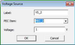
To add a new Fixed-Potential PEC group to a project, right-click on "Fixed-Potential PEC Objects" on the Navigation Tree, and select "Insert New PEC..." From the PEC dialog, you can change the default red color and set a value for the "Voltage" in Volts.
| |
You can define any solid or surface object as a fixed-potential PEC object. |
Dielectric/Magnetic Materials
In electromagnetic analysis, a general dielectric material is represented by four constitutive material parameters: relative permittivity εr, relative permeability μr, electric conductivity σ and magnetic conductivity σm. In EM.Ferma, you can define dielectric materials for electrostatic analysis and magnetic (permeable) materials for magnetostatic analysis from the same section of the Navigation Tree titled "Dielectric/Magnetic Materials". For a dielectric material, you specify the relative permittivity εr and electric conductivity σ. For a magnetic material, you specify the relative permeability μr.
To add a new dielectric or magnetic material group to a project, right-click on "Dielectric/Magnetic Materials" on the Navigation Tree, and select "Insert New Dielectric..." From the Dielectric Dialog, you can change the default green color of a material group or set the values of the material parameters.
| |
You can define any solid object as a dielectric or magnetic material object. |
Volume Charge Sources
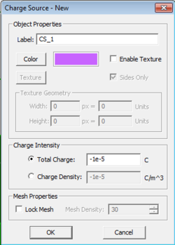
You can define volume charge sources with a specified charge density in C/m3 confined to certain region of your project. You use EM.Cube's solid objects to define volume charge sources. All the charge sources belonging to the same group have the same color and same charge density value. The charge density can be positive or negative. To add a new charge source group to a project, right-click on "Volume Charges" on the Navigation Tree, and select "Insert New Charge Source..." From the Charge Source Dialog, you can change the default purple color of the source group or set the values of the Charge Density.
Volume Current Sources
You can define volume current sources with a specified current density in A/m2 confined to certain region of your project. Note that current density is a vectorial quantity and has a magnitude and unit direction vector. You use EM.Cube's solid objects to define volume current sources. All the volume current sources belonging to the same group have the same color and same current density magnitude and unit vector.
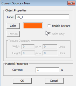
To add a new volume current source group to a project, right-click on "Volume Currents" on the Navigation Tree, and select "Insert New Current Source..." From the Volume Current Source Dialog, you can change the default brown color of the source group or set the values of the Current Density magnitude and unit direction vector components. The default direction vector is z-directed.
Wire Current Sources
EM.Ferma allows you to define idealized wire current sources. You can use this source type to model filament currents or coils. Wire currents are defined using only line and polyline objects. You also need to define a current value I in Amperes and a wire radius r in the project units. The line or polyline object is then approximated as a volume current with a current density of J = I/(πr2) flowing along the line or polyline side's direction. All the wire current sources belonging to the same group have the same color, same current value and same wire radius. The direction of the current can be reversed in wire current sources.
To add a new wire current source group to a project, right-click on "Wire Currents" on the Navigation Tree, and select "Insert New Current Source..." From the Wire Current Source Dialog, you can change the default brown color of the source group or set the values of the Current and Wire Radius. There is also a check box for "Reverse Current Direction". Note that this will reverse the direction of all the wire currents belonging to the same group. When you draw a line or polyline object under a wire current group in the Navigation Tree, you will notice that direction arrows are placed on the drawn CAD object. You can draw any curve object in the project workspace and convert it to a polyline using EM.Cube's Polygonize Tool.
| |
If you draw [[[Curve Objects]]] under a wire current group, they will be permanently converted to polyline objects before running the simulation engine. |
Permanent Magnets
A permanent magnet is typically a ferromagnetic material with a fixed inherent magnetization vector. As a result, it can be used as a source in an magnetostatic problem. When a permeable material has a permanent magnetization, the following relationship holds:
[math] \mathbf{B(r)} = {\mu} (\mathbf{H(r)} + \mathbf{M(r)} ) [/math]
where M(r) is the magnetization vector. In SI units system, the magnetic field H and magnetization M both have the same units of A/m.
It can be shown that for magnetostatic analysis, the effect of the permanent magnetization can be modeled as an equivalent volume current source:
[math] \mathbf{J_{eq}(r)} = \nabla \times \mathbf{M(r)} [/math]
If the magnetization vector is uniform and constant inside the volume, then its curl is zero everywhere inside the volume except on its boundary surface. In this case, the permanent magnetic can be effectively modeled by an equivalent surface current density on the surface of the permanent magnetic object:
[math] \mathbf{J_{s,eq}(r)} = \mathbf{M(r)} \times \hat{\mathbf{n}} [/math]
where [math] \hat{\mathbf{n}} [/math] is the unit outward normal vector at the surface of the permanent magnet object. Note that the volume of the permanent magnet still acts as a permeable material in the magnetostatic analysis.
To add a new permanent magnet source group to a project, right-click on "Permanent Magnets" on the Navigation Tree, and select "Insert New Permanent Magnet Source..." From the Permanent Magnet Source Dialog, you can change the default purple color of the source group or set the values of the relative permeability, Magnetization magnitude and unit direction vector components. The default direction vector is z-directed.
Computational Domain and Discretization
The Domain Box
In EM.Ferma, the Poisson or Laplace equations are solved subject to boundary conditions using the Finite Difference technique. As a result, you need to specify a finite computational domain and then specify the domain boundary conditions. EM.Ferma's computational domain defines where the domain boundary condition will be specified. A default domain box is always placed in the project workspace as soon as you draw your first object. The domain can be seen as a blue cubic wireframe that surrounds all of the CAD objects in the project workspace.
To modify the domain settings, click the Domain button of the Simulate Toolbar or right-click on "3D Static Domain" entry in the Navigation Tree and select "Domain Settings..." from the contextual menu. In the Domain Settings Dialog, the computational domain can be defined in two different ways: Default and Custom. The default type places an enclosing box with a specified offset from the largest bounding box of your project's CAD objects. The default offset value is 20 project units, but you can change this value arbitrarily. The custom type defines a fixed domain box by specifying the coordinates of its two opposite corners labeled Min and Max in the world coordinate system.
Domain Boundary Conditions
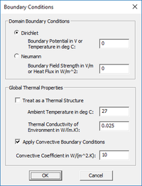
EM.Ferma allows you to specify the electric potential boundary conditions on the domain box. Two options are available. The Dirichlet boundary condition is the default option and is specified as a fixed potential value on the surface of the domain walls. By default, this value is 0 Volts. The Neumann boundary condition specifies the normal derivative of the electric scalar potential on the surface of the domain walls. This is equivalent to the normal electric field component on the domain walls and its value is specified in V/m. The magnetostatic simulation engine always assumes Dirichlet domain boundary conditions and sets the values of the magnetic vector potential to zero on all the domain walls. To modify the boundary conditions, right-click on "Boundary Conditions" in the Navigation Tree, and select "Boundary Conditions..." from the contextual menu to open the Boundary Conditions Dialog.
The Static Mesh
The Finite Difference technique discretizes the computational domain using a 3D rectangular grid. EM.Ferma generates a fixed-cell mesh. This means that the extents of the mesh cells along the principal axes are fixed: Δx, Δy, Δz. By default, the mesh cell size is set to one unit project along all the three directions (with Δx = Δy = Δz). To modify the cell size, click the Mesh Settings button of the Simulate Toolbar or right-click on "Static Mesh" in the Navigation Tree, and select "Mesh Settings..." from the contextual menu to open the Mesh Settings Dialog.
| |
To obtain accurate results, it is highly recommended to use a square mesh as much as possible. |
Running Static Simulations in EM.Ferma
Two Simulation Engines
EM.Ferma has two independent but functionally similar static simulation engines: Electrostatic and Magnetostatic. The electrostatic engine solves the electric form of Poisson's equation for electric scalar potential subject to electric field boundary conditions, in the presence of electric sources (volume charges and fixed-potential PEC blocks) and dielectric material media. The magnetostatic engine solves the magnetic form of Poisson's equation for magnetic vector potential subject to magnetic field boundary conditions, in the presence of magnetic sources (wire and volume currents and permanent magnetic blocks) and magnetic material media.
In EM.Ferma you don't have to select any specific simulation engine. The program looks at the types sources and material objects present in your project workspace and then it determines whether an electrostatic analysis or a magnetostatic analysis or possibly both should be performed. When there are only electric sources present, you will get nonzero electric fields and zero magnetic fields. When there are only magnetic sources present, you will get nonzero magnetic fields and zero electric fields.
Simulation Modes
EM.Ferma currently offers three different simulation modes: Analysis, Parametric Sweep and Optimization. An "Analysis" is a single-shot finite difference solution of your static structure. The structure is first discretized using a fixed-cell mesh and the Poisson equation is solved numerically everywhere in your computational domain. The field and potential values at each mesh node are computed and the specified observables are written into data files.
In a "Parametric Sweep", one ore more variables are varied at the specified steps(s). This means that you must first define one or more variables in your projects. Variables can be associated with CAD object properties like dimensions, coordinates, rotation angles, etc. or with material properties or source properties. For each single variable sample or each combination of variable samples, first all the associated CAD object properties, material properties or source properties are updated in the project workspace. Then is a finite difference solution of your updated static structure is computed and parametric sweep proceeds to the next variable sample or combination.
Static Simulation Engine Settings
EM.Ferma currently uses a single iterative linear system solver based on the stabilized Bi-Conjugate Gradient (BiCG) method to solve the matrix equations which result from the discretization of Poisson's equation. You can specify some numerical parameters related to the Bi-CG solver. To do that, you need to open the Simulation Engine Settings Dialog by clicking the "Settings" button located next to the "Select Engine" drop-down list. From this dialog you can set the maximum number of BiCG iterations, which has a default value of 10,000. You can also set a value for "Convergence Error". The default value for electrostatic analysis is 0.001. For magnetostatic analysis, the specified value of convergence error is reduced by a factor 1000 automatically. Therefore, the default convergence error in this case is 1e-6.
Observables in EM.Ferma
At the end of an electrostatic simulation, the electric field and electric scalar potential values are computed at all the mesh grid points of the entire computational domain. At the end of an magnetostatic simulation, the magnetic field and magnetic vector potential values are computed at all the grid nodes. The field and potential values are written into output data files and can be visualized on the screen only if you define a field sensor observable. In the absence of a defined observable, the static simulation will be carried out and completed, but to action will take place.
Defining Field Sensors
Just like other EM.CUBE Modules, EM.Ferma has a Field Sensor observable, which plots 3D visualizations of electric and magnetic field components on a specified plane. However, unlike the other modules, EM.Ferma field sensors have two additional plots for electric scalar potential and magnitude of the magnetic vector potential. These are called the "EPot" and "HPot" nodes on the Navigation Tree. To define a Field Sensor, right-click on "Field Sensors" in the Navigation Tree and select "Insert New Observable..." from the contextual menu. The Field Sensor dialog allows the user to select the direction of the sensor (X, Y, Z), visualization type, and whether E-field output or H-field output will be shown during a sweep analysis.
The E-fields and H-fields are computed at each mesh node within the specified 2D Field Sensor plane. In other words, the resolution of the Field Sensor is controlled by the mesh resolution.
Defining Field Integrals
It is often needed to compute integrals of the electric or magnetic fields to define other related quantities. The following table shows some of widely used field integrals:
| Quantity | Field Integral |
|---|---|
| Voltage | [math] V = \int_C \mathbf{E(r)} . \mathbf{dl} [/math] |
| Current | [math] I = \int_{C_o} \mathbf{H(r)} . \mathbf{dl} [/math] |
| Electric Flux | [math] \Phi_E = \int\int_{S_o} \mathbf{D(r)} . \mathbf{ds} = \int\int_{S_o} \epsilon \mathbf{E(r)} . \mathbf{ds} [/math] |
| Magnetic Flux | [math] \Phi_H = \int\int_S \mathbf{B(r)} . \mathbf{ds} = \int\int_S \mu \mathbf{H(r)} . \mathbf{ds} [/math] |
| Electric Energy | [math] W_E = \int \int \int_V \epsilon \vert \mathbf{E(r)} \vert ^2 dv [/math] |
| Magnetic Energy | [math] W_H = \int\int\int_V \mu \vert \mathbf{H(r)} \vert ^2 dv [/math] |
| Capacitance | [math] C = Q/V = \int\int_{S_o} \epsilon \mathbf{E(r)} . \mathbf{ds} / \int_C \mathbf{E(r)} . \mathbf{dl} [/math] |
| Inductance | [math] L = \Phi_H/I = \int\int_S \mu \mathbf{H(r)} . \mathbf{ds} / \int_{C_o} \mathbf{H(r)} . \mathbf{dl} [/math] |
In the above table, C represents an open curve (path), Co represents a closed curve (loop), S represents an open surface like a plane, So represents a closed surface like a box, and V represents a volume.
In EM.Ferma, you can define a path integral along a line segment that is parallel to one of the three principal axes, or a loop integral on a rectangle that is parallel to one of the principal planes. You can also define flux planes or flux boxes. All this is done from the same Field Integral Dialog. To define a Field Integral, right-click on "Field Integrals" in the Navigation Tree and select "Insert New Observable..." from the contextual menu. The Integral Type drop-down list gives five options:
| Field Integral Type | Output Data File(s) |
|---|---|
| Voltage Path | voltage.DAT |
| Current Loop | current.DAT |
| Flux Plane | flux_H.DAT |
| Flux Box | flux_E.DAT |
| Energy Box | energy_E.DAT & energy_H.DAT |
The domain of the field integral is set using the "Integration Box Coordinates" section of the Field Integral dialog. Box domains are specified by the coordinates of two opposite corners. Voltage Path requires a line; therefore, two of the coordinates of the two corners must be identical. Otherwise, an error message will pop up. For example, (0, 0, 0) for Corner 1 and (10, 0, 0) for Corner 2 define a Z-directed line segment. Current Loop requires a rectangle; therefore, one of the coordinates of the two corners must be identical. For example, (0, 0, 0) for Corner 1 and (10, 10, 0) for Corner 2 define a rectangle in the XY plane.
After the completion of a static simulation, the result of the field integrals are written into ".DAT" data files. These files can be accessed using EM.Cube's Data Manager.
| |
If you define a single Flux Box observable and a single Voltage Path observable for your static project, the Capacitance is calculated and written to "capacitance.DAT" data file. |
| |
If you define a single Flux Plane observable and a single Current Loop observable for your static project, the Inductance is calculated and written to "inductance .DAT" data file. |
2D Quasi-Static Solution of Transmission Lines
EM.Ferma features a 2D solution mode where the model is treated as a longitudinally infinite structure at a list of specified 2D Solution Planes. The 2D planes are defined by a Field Sensor definition that already exists in the project.
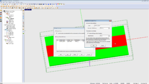
To explore EM.Ferma's 2D mode, right-click on "2D Solution Planes" in the navigation tree and select "2D Domain Settings...". In the 2D Static Domain dialog, enable the checkbox labeled "Treat Structure as Longitudinally Infinite across Each 2D Plane Specified Below". The user is then able to Add or Edit 2D Solution Plane definitions to the solution list.
Setting up a Transmission Line Simulation
To perform a Transmission Line simulation, first turn on Quasistatic simulation mode for a selected 2D Solution Plane, as shown in the figure at right. If an analysis is run with this option checked, the characteristic impedance (Z0) and Effective Epsilon will be computed for the corresponding 2D Solution Plane. This output can be found in appropriately-named text files in the project directory upon completion of the simulation. Fields and potentials at the selected 2D plane will still be computed. Many 2D quasistatic solutions can be obtained in the same analysis, if for example, your design contains many types of transmission lines.
Quasistatic analysis can only be performed with a Dirichlet boundary condition with 0V specified on the boundaries.
For a step-by-step demonstration (including transmission line optimization), take a look at this video on our YouTube channel: EM.CUBE Microstrip Optimization
Transmission Line Characteristics
In EM.Ferma's quasistatic mode, transmission-line parameters Z0 and EpsEff are computed, in addition to output due to the Field Sensor, which is required to define the 2D solution plane. Text files corresponding to these observables will be placed in the project's working directory after each analysis.
Simulation Examples / Gallery
Version History
- First available in EM.CUBE 14.2
