Difference between revisions of "NeoScan Manual Part G: Appendix II: Troubleshooting"
(→Low Power / No Power) |
(→NeoScan Optical Bench Manager Program Not Responding) |
||
| (19 intermediate revisions by the same user not shown) | |||
| Line 16: | Line 16: | ||
</p> | </p> | ||
</li> | </li> | ||
| − | <ul> | + | </ul> |
Therefore, | Therefore, | ||
| Line 36: | Line 36: | ||
</p> | </p> | ||
</li> | </li> | ||
| − | <ol> | + | </ol> |
| + | |||
| + | <center>[[Image:neoscanfig_A_II_1.png|thumb|center|600px|<i><b>Figure A-II.1</b>: NeoScan Optical Bench Manager indicating that the total return power is too low.</i>]]</center> | ||
=== Low EO Signal / No Signal === | === Low EO Signal / No Signal === | ||
| Line 63: | Line 65: | ||
</p> | </p> | ||
</li> | </li> | ||
| − | <ul> | + | </ul> |
Therefore, | Therefore, | ||
| Line 88: | Line 90: | ||
</p> | </p> | ||
</li> | </li> | ||
| − | <ol> | + | </ol> |
| + | |||
| + | <center>[[Image:neoscanfig_A_II_2.png|thumb|center|400px|<i><b>Figure A-II.2</b>: Spectrum Analyzer cannot detect any EO signal.</i>]]</center> | ||
=== Missing [[NeoScan]] Program Icons === | === Missing [[NeoScan]] Program Icons === | ||
| − | [[NeoScan]] Program icons on desktop are missing. | + | [[Image:icon_all.png|right]] [[NeoScan]] Program icons on desktop are missing. |
[[NeoScan]] system control and monitoring programs including: [[NeoScan]] Optical Bench Manager (NeoScanOBM.exe), [[NeoScan]] Mapping Utility (NeoScanMAP.exe), and [[NeoScan]] Visualization Utility (NeoScanPlot.exe) are located in C:\Program Files (x86)\[[NeoScan]]. You can create a shortcut. | [[NeoScan]] system control and monitoring programs including: [[NeoScan]] Optical Bench Manager (NeoScanOBM.exe), [[NeoScan]] Mapping Utility (NeoScanMAP.exe), and [[NeoScan]] Visualization Utility (NeoScanPlot.exe) are located in C:\Program Files (x86)\[[NeoScan]]. You can create a shortcut. | ||
| − | + | === Lock-in Amplifier Not Found === | |
| − | + | ||
If [[NeoScan]] Mapping Utility cannot communicate with lock-in amplifier or lock-in amplifier is not responding, then | If [[NeoScan]] Mapping Utility cannot communicate with lock-in amplifier or lock-in amplifier is not responding, then | ||
| − | + | <ul> | |
| − | + | <li> | |
| − | + | <p> | |
| − | + | Lock-in amplifier is off. | |
| − | + | </p> | |
| + | </li> | ||
| + | <li> | ||
| + | <p> | ||
| + | Or lock-in amplifier is not connected to the [[NeoScan]] system through the USB Hub. | ||
| + | </p> | ||
| + | </li> | ||
| + | <li> | ||
| + | <p> | ||
| + | Or GPIB address for lock-in amplifier Visa is not correct. | ||
| + | </p> | ||
| + | </li> | ||
| + | </ul> | ||
Consequently, the user is prompted with a warning message as shown in Figure A-II.3. | Consequently, the user is prompted with a warning message as shown in Figure A-II.3. | ||
| + | |||
| + | <center>[[Image:neoscanfig_A_II_3.png|thumb|center|350px|<i><b>Figure A-II.3</b>: Warning message when lock-in amplifier is not responding.</i>]]</center> | ||
Therefore, | Therefore, | ||
| − | + | <ol> | |
| + | <li> | ||
| + | <p> | ||
| + | Check whether lock-in amplifier is on. | ||
| + | </p> | ||
| + | </li> | ||
| + | <li> | ||
| + | <p> | ||
| + | Or check if GPIB-USB cable from the (rear panel of) lock-in amplifier is connected to the USB Hub (Figure A-II.4). | ||
| + | </p> | ||
| − | + | <center>[[Image:neoscanfig_A_II_4.png|thumb|center|500px|<i><b>Figure A-II.4</b>: Rear Panel of Stanford Research Systems SR844 RF Lock-In Amplifier.</i>]]</center> | |
| + | </li> | ||
| + | <li> | ||
| + | <p> | ||
| + | Press “Hardware Settings” tab in [[NeoScan]] Mapping Utility program. Put down the Visa menu and select the appropriate GPIB address for lock-in amplifier Visa The default is GPIB0::8::INST (See Figure A-II.5). | ||
| + | </p> | ||
| − | + | <center>[[Image:neoscanfig_A_II_5.png|thumb|center|500px|<i><b>Figure A-II.5</b>: Setting lock-in amplifier parameters in NeoScan Mapping Utility.</i>]]</center> | |
| − | + | </li> | |
| − | + | <li> | |
| + | <p> | ||
| + | Disconnect the GPIB-USB cable from the USB Hub port and then reconnect it again to the same port. | ||
| + | </p> | ||
| + | </li> | ||
| + | </ol> | ||
If the problem persists, turn off lock-in amplifier and then turn it on. Then Disconnect the GPIB-USB cable from the USB Hub port and then reconnect it again to the same port. | If the problem persists, turn off lock-in amplifier and then turn it on. Then Disconnect the GPIB-USB cable from the USB Hub port and then reconnect it again to the same port. | ||
| − | + | <ul> | |
| + | <li> | ||
| + | It is important to note that failed to respond properly to this issue, it may cause the system hung up, in which you may restart the whole [[NeoScan]] system and control computer. | ||
| + | </li> | ||
| + | </ul> | ||
| − | + | === Translation Stage Not Responding === | |
| + | If [[NeoScan]] Mapping Utility cannot communicate with the translation stage system, then | ||
| − | + | <ul> | |
| − | + | <li> | |
| − | + | <p> | |
| − | + | The power is off. | |
| − | + | </p> | |
| + | </li> | ||
| + | <li> | ||
| + | <p> | ||
| + | Or the X Linear Translation Stage is not connected to the [[NeoScan]] system (USB Hub). | ||
| + | </p> | ||
| + | </li> | ||
| + | </ul> | ||
Consequently, the user is prompted with warning message as shown in Figure A-II.6. | Consequently, the user is prompted with warning message as shown in Figure A-II.6. | ||
| − | + | <center>[[Image:neoscanfig_A_II_6.png|thumb|center|350px|<i><b>Figure A-II.6</b>: Dialog window when Translation Stage is not responding.</i>]]</center> | |
| − | + | ||
Therefore, | Therefore, | ||
| − | + | <ol> | |
| − | + | <li> | |
| − | + | <p> | |
| − | + | Check whether the Linear Translation Stage power is on. | |
| − | + | </p> | |
| − | + | </li> | |
| − | + | <li> | |
| + | <p> | ||
| + | Check if the translation stage cablings are correct. | ||
| + | </p> | ||
| + | </li> | ||
| + | <li> | ||
| + | <p> | ||
| + | Check if the USB cable from X the Linear Translation Stage port is connected to the USB Hub. | ||
| + | </p> | ||
| + | </li> | ||
| + | <li> | ||
| + | <p> | ||
| + | Disconnect the USB cable from the USB Hub port and then reconnect it again to the same port. | ||
| + | </p> | ||
| + | </li> | ||
| + | </ol> | ||
If the problem persists, turn off the programmable motion controller and then turn it on. Then Disconnect the USB cable from the USB Hub port and then reconnect it again to the same port. | If the problem persists, turn off the programmable motion controller and then turn it on. Then Disconnect the USB cable from the USB Hub port and then reconnect it again to the same port. | ||
| − | + | <ul> | |
| + | <li> | ||
| + | It is important to note that failed to respond properly to this issue, it may cause the system to hung, in which you may restart the whole [[NeoScan]] system and control computer. | ||
| + | </li> | ||
| + | </ul> | ||
| − | + | === Translation Stage Has Hung Up === | |
| − | + | ||
When the XY Linear Translation Stage hits the edge sensors of the base, it will hang up and stops functioning (see section A.4). In this situation, | When the XY Linear Translation Stage hits the edge sensors of the base, it will hang up and stops functioning (see section A.4). In this situation, | ||
| − | + | <ul> | |
| − | + | <li> | |
| − | + | <p> | |
| − | + | Reset the Linear Translation Stages by switching it off and then turning it on, | |
| − | + | </p> | |
| − | + | </li> | |
| + | <li> | ||
| + | <p> | ||
| + | Disconnect the USB cable from the USB Hub port and then reconnect it again to the same port. | ||
| + | </p> | ||
| + | </li> | ||
| + | </ul> | ||
| + | === Optimization Utility Program Not Functioning === | ||
[[NeoScan]] Optimization Utility program stops functioning if | [[NeoScan]] Optimization Utility program stops functioning if | ||
| − | + | <ul> | |
| − | + | <li> | |
| − | + | <p> | |
| − | + | The Lock-in Amplifier is off. | |
| − | + | </p> | |
| + | </li> | ||
| + | <li> | ||
| + | <p> | ||
| + | Or the Lock-in Amplifier is not connected to the [[NeoScan]] system through the USB Hub. | ||
| + | </p> | ||
| + | </li> | ||
| + | <li> | ||
| + | <p> | ||
| + | Or GPIB address for the Lock-in Amplifier Visa is not correct. | ||
| + | </p> | ||
| + | </li> | ||
| + | </ul> | ||
Consequently, information panel warns that spectrum analyzer “Not Found” as shown in Figure A-II.7. | Consequently, information panel warns that spectrum analyzer “Not Found” as shown in Figure A-II.7. | ||
| + | |||
| + | <center>[[Image:neoscanfig_A_II_7.png|thumb|center|400px|<i><b>Figure A-II.7</b>: Dialog .</i>]]</center> | ||
Therefore, | Therefore, | ||
| − | + | <ol> | |
| − | + | <li> | |
| − | + | <p> | |
| − | + | Check whether the Lock-in Amplifier is on. | |
| − | + | </p> | |
| + | </li> | ||
| + | <li> | ||
| + | <p> | ||
| + | Check if the GPIB-USB cable from the Lock-in Amplifier port is connected to the USB Hub (Figure AII-.8). | ||
| + | </p> | ||
| + | </li> | ||
| + | <li> | ||
| + | <p> | ||
| + | Disconnect the USB cable from the USB Hub port and then reconnect it again to the same port. | ||
| + | </p> | ||
| + | </li> | ||
| + | </ol> | ||
| + | <center>[[Image:neoscanfig_A_II_8.png|thumb|center|400px|<i><b>Figure A-II.8</b>: Cor.</i>]]</center> | ||
| − | + | === Incorrect Working Folder (Directory) === | |
Make sure NoeScan Mapping Utility or [[NeoScan]] Plot Utility programs are pointing to the correct working folder (Figure A-II.9). | Make sure NoeScan Mapping Utility or [[NeoScan]] Plot Utility programs are pointing to the correct working folder (Figure A-II.9). | ||
| − | + | <center>[[Image:neoscanfig_A_II_9.png|thumb|center|600px|<i><b>Figure A-II.9</b>: Correct working or project and folder path.</i>]]</center> | |
| + | |||
| + | <ol> | ||
| + | <li> | ||
| + | <p> | ||
| + | In NoeScan Mapping Utility use the browse button to set “Working Folder” path to | ||
C:\Users\[[NeoScan|neoscan]]\Documents\[[NeoScan]]\Projects. | C:\Users\[[NeoScan|neoscan]]\Documents\[[NeoScan]]\Projects. | ||
| − | + | </p> | |
| − | + | </li> | |
| + | <li> | ||
| + | <p> | ||
| + | In NoeScan Plot Utility use the browse button to set “Project Folder” path to | ||
C:\Users\[[NeoScan|neoscan]]\Documents\[[NeoScan]]\Projects. | C:\Users\[[NeoScan|neoscan]]\Documents\[[NeoScan]]\Projects. | ||
| + | </p> | ||
| + | </li> | ||
| + | </ol> | ||
| − | + | === Irregular Patterns in 2D Phase Plots === | |
| − | + | ||
| − | + | ||
| − | + | ||
| − | + | ||
If there are irregular patterns in 2D Phase plots in [[NeoScan]] Plot Utility program, as shown in Figure A-II.10, it might be the case that there is no synchronization between scan instruments. | If there are irregular patterns in 2D Phase plots in [[NeoScan]] Plot Utility program, as shown in Figure A-II.10, it might be the case that there is no synchronization between scan instruments. | ||
| + | |||
| + | <center>[[Image:neoscanfig_A_II_10.png|thumb|center|400px|<i><b>Figure A-II.10</b>: An example of irregular pattern in 2D Phase plot when scan instruments are not synchronized.</i>]]</center> | ||
Therefore, | Therefore, | ||
| − | + | <ol> | |
| − | + | <li> | |
| − | + | <p> | |
| − | + | Make sure all 10 MHz reference cables are connected appropriately (in the back of the corresponding instruments) and the connectors are not loose. | |
| − | + | </p> | |
| + | </li> | ||
| + | <li> | ||
| + | <p> | ||
| + | Check if the BNC cables are fine. | ||
| + | </p> | ||
| + | </li> | ||
| + | <li> | ||
| + | <p> | ||
| + | Make sure “Modulation Generator” key in 100 MHz signal generator for lock-in amplifier is off. | ||
| + | </p> | ||
| + | </li> | ||
| + | </ol> | ||
| + | === Wiggling Power Levels === | ||
| − | A-II. | + | If the FC/APC connector is not clean (Figure A-II.11), despite probe optimization the return power and the optimization power graphs appears wiggling as shown in Figure A-II.12. |
| − | + | <center> | |
| + | [[Image:neoscanfig_A_II_11.png|thumb|center|600px|<i><b>Figure A-II.11</b>: FC/APC connector of a PM Fiber under microscope: A dirt seen as a black mark on the fiber end connector (left). A clean fiber (right).</i>]] | ||
| + | <br> | ||
| + | [[Image:neoscanfig_A_II_12.png|thumb|center|600px|<i><b>Figure A-II.12</b>: Wiggling return power and the optimization power graphs for a PM fiber with a dirt on the fiber end connector.</i>]] | ||
| + | </center> | ||
Therefore | Therefore | ||
| − | + | <ol> | |
| + | <li> | ||
| + | <p> | ||
| + | Detach the fiber connector from fiber port of the [[NeoScan]] system. | ||
| + | </p> | ||
| + | </li> | ||
| + | <li> | ||
| + | <p> | ||
| + | Use a dry cleaning cloth (reel-based cassette cleaner) to remove dirt, dust, and oil from connector end faces (Figure A-II.13). | ||
| + | </p> | ||
| + | </li> | ||
| + | <li> | ||
| + | <p> | ||
| + | Attach the fiber connector to the fiber port of the [[NeoScan]] system. | ||
| + | </p> | ||
| + | </li> | ||
| + | <li> | ||
| + | <p> | ||
| + | Perform a probe optimization. | ||
| + | </p> | ||
| + | </li> | ||
| + | </ol> | ||
| − | + | <center>[[Image:neoscanfig_A_II_13.png|thumb|center|600px|<i><b>Figure A-II.13</b>: Cleaning a connector end face using a dry cleaning cloth reel-based cassette cleaner</i>]]</center> | |
| − | + | === [[NeoScan]] Optical Bench Manager Program Not Responding === | |
| − | + | When the A/D and D/A convertor drivers are not detected by the system, NoeScan Optical Bench Manager program prompts a warning as shown in Figure AII-14. Or sometimes NoeScan Optical Bench Manager program does not respond. | |
| − | |||
| − | + | <center>[[Image:neoscanfig_A_II_14.png|thumb|center|300px|<i><b>Figure A-II.14</b>: Warning massage for missing AD and DA addresses..</i>]]</center> | |
To solve the problem, | To solve the problem, | ||
| − | + | <ol> | |
| + | <li> | ||
| + | <p> | ||
| + | Turn off the [[NeoScan]] system and turn it on again. | ||
| + | </p> | ||
| + | </li> | ||
| + | <li> | ||
| + | <p> | ||
| + | Reboot the control computer. | ||
| + | </p> | ||
| + | </li> | ||
| + | <li> | ||
| + | <p> | ||
| + | Go to Window Application (Program) or “Measurement Computing” folder and click on “Instacal” (Figure A-II.15). | ||
| + | </p> | ||
| − | + | <center> | |
| + | [[Image:neoscanfig_A_II_15.png|thumb|center|600px|<i><b>Figure A-II.15</b>: Start the Instacal driver controller program.</i>]] | ||
| + | </center> | ||
| + | </li> | ||
| + | <li> | ||
| + | <p> | ||
| + | You may be prompted with a message box as shown in Figure A-II.16 saying that the previous board name has not been deleted. Press “OK” button. | ||
| + | </p> | ||
| − | + | <center> | |
| + | [[Image:neoscanfig_A_II_16.png|thumb|center|600px|<i><b>Figure A-II.16</b>: Configure the Instacal driver controller program.</i>]] | ||
| + | </center> | ||
| + | </li> | ||
| + | <li> | ||
| + | <p> | ||
| + | The “Instacal” driver interface will list A/D and D/A board names – e.g. USB-1608FS board and USB-3114 (Figure A-II.17). | ||
| + | </p> | ||
| − | + | <center> | |
| + | [[Image:neoscanfig_A_II_17.png|thumb|center|400px|<i><b>Figure A-II.17</b>: Instacal driver controller program list A/D and D/A board names.</i>]] | ||
| + | </center> | ||
| + | </li> | ||
| + | <li> | ||
| + | <p> | ||
| + | Select USB-3114 and double click on it. | ||
| + | </p> | ||
| + | </li> | ||
| + | <li> | ||
| + | <p> | ||
| + | In USB-3114 Board Configuration window use the dropdown list and set at the D/A Ranges to +/-10V (default is 0-10V)as shown in Figure A-II-18. | ||
| + | </p> | ||
| − | + | <center> | |
| + | [[Image:neoscanfig_A_II_18.png|thumb|center|400px|<i><b>Figure A-II.18</b>: Instacal driver controller program list A/D and D/A board names.</i>]] | ||
| + | </center> | ||
| + | </li> | ||
| + | <li> | ||
| + | <p> | ||
| + | Close “Instacal” driver interface and open [[NeoScan]] Optical Bench Manager program. | ||
| + | </p> | ||
| + | </li> | ||
| + | <li> | ||
| + | <p> | ||
| + | If the “Instacal” driver interface does not list A/D and D/A board names as indicated in Figure A-II-19. | ||
| + | </p> | ||
| − | + | <center> | |
| + | [[Image:neoscanfig_A_II_19.png|thumb|center|400px|<i><b>Figure A-II.19</b>: Instacal driver controller program cannot detect A/D and D/A converters.</i>]] | ||
| + | </center> | ||
| − | + | <ol type="a"> | |
| − | + | <li> | |
| − | + | <p> | |
| − | + | Double click on program “MCCRegistryFix3.exe”. You can find it in C:\ProgramData folder. | |
| − | + | </p> | |
| − | + | </li> | |
| − | + | <li> | |
| − | + | <p> | |
| − | + | Unplug the USB cable from the [[NeoScan]] Optical Mainframe. | |
| − | + | </p> | |
| − | + | </li> | |
| − | + | <li> | |
| − | + | <p> | |
| − | + | Plug the USB cable from the [[NeoScan]] Optical Mainframe. | |
| + | </p> | ||
| + | </li> | ||
| + | <li> | ||
| + | <p> | ||
| + | Run “Instacal” program again. | ||
| + | </p> | ||
| + | </li> | ||
| + | <ol> | ||
Latest revision as of 17:09, 9 March 2017
Contents
- 1 Appendix II: Troubleshooting
- 1.1 Low Power / No Power
- 1.2 Low EO Signal / No Signal
- 1.3 Missing NeoScan Program Icons
- 1.4 Lock-in Amplifier Not Found
- 1.5 Translation Stage Not Responding
- 1.6 Translation Stage Has Hung Up
- 1.7 Optimization Utility Program Not Functioning
- 1.8 Incorrect Working Folder (Directory)
- 1.9 Irregular Patterns in 2D Phase Plots
- 1.10 Wiggling Power Levels
- 1.11 NeoScan Optical Bench Manager Program Not Responding
Appendix II: Troubleshooting
Low Power / No Power
If NeoScan optical mainframe is on;but the total return power and the polarization power are too low (Figure A-II.1) – or there is no power, then
-
Either the probe is not connected to Neoscan optical mainframe.
-
Or the probe is defective.
Therefore,
-
Check the connectors.
-
Inspect the probe.
-
If the connection is fine and still there is no power, try another probe.

Low EO Signal / No Signal
If NeoScan optical mainframe is on, yet, the EO signal is too low or there is no signal (Figure A-II.2), then
-
The probe is not connected to Neoscan optical mainframe.
-
Or the probe is defective.
-
Or the cables are lossy or defective.
-
Or operating environment is too noisy.
Therefore,
-
Check the connectors.
-
Check the cables.
-
Inspect the probe.
-
If all the connectors and cables are fine, and still there is no signal, try another probe

Missing NeoScan Program Icons

NeoScan system control and monitoring programs including: NeoScan Optical Bench Manager (NeoScanOBM.exe), NeoScan Mapping Utility (NeoScanMAP.exe), and NeoScan Visualization Utility (NeoScanPlot.exe) are located in C:\Program Files (x86)\NeoScan. You can create a shortcut.
Lock-in Amplifier Not Found
If NeoScan Mapping Utility cannot communicate with lock-in amplifier or lock-in amplifier is not responding, then
-
Lock-in amplifier is off.
-
Or lock-in amplifier is not connected to the NeoScan system through the USB Hub.
-
Or GPIB address for lock-in amplifier Visa is not correct.
Consequently, the user is prompted with a warning message as shown in Figure A-II.3.

Therefore,
-
Check whether lock-in amplifier is on.
-
Or check if GPIB-USB cable from the (rear panel of) lock-in amplifier is connected to the USB Hub (Figure A-II.4).
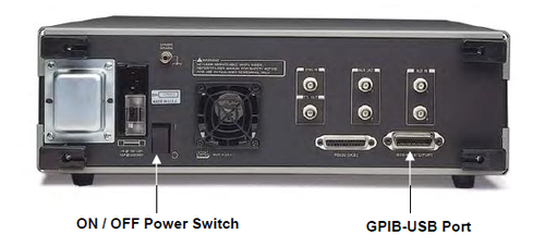 Figure A-II.4: Rear Panel of Stanford Research Systems SR844 RF Lock-In Amplifier.
-
Press “Hardware Settings” tab in NeoScan Mapping Utility program. Put down the Visa menu and select the appropriate GPIB address for lock-in amplifier Visa The default is GPIB0::8::INST (See Figure A-II.5).
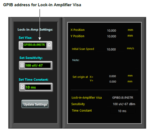 Figure A-II.5: Setting lock-in amplifier parameters in NeoScan Mapping Utility.
 -
Disconnect the GPIB-USB cable from the USB Hub port and then reconnect it again to the same port.


If the problem persists, turn off lock-in amplifier and then turn it on. Then Disconnect the GPIB-USB cable from the USB Hub port and then reconnect it again to the same port.
- It is important to note that failed to respond properly to this issue, it may cause the system hung up, in which you may restart the whole NeoScan system and control computer.
Translation Stage Not Responding
If NeoScan Mapping Utility cannot communicate with the translation stage system, then
-
The power is off.
-
Or the X Linear Translation Stage is not connected to the NeoScan system (USB Hub).
Consequently, the user is prompted with warning message as shown in Figure A-II.6.

Therefore,
-
Check whether the Linear Translation Stage power is on.
-
Check if the translation stage cablings are correct.
-
Check if the USB cable from X the Linear Translation Stage port is connected to the USB Hub.
-
Disconnect the USB cable from the USB Hub port and then reconnect it again to the same port.
If the problem persists, turn off the programmable motion controller and then turn it on. Then Disconnect the USB cable from the USB Hub port and then reconnect it again to the same port.
- It is important to note that failed to respond properly to this issue, it may cause the system to hung, in which you may restart the whole NeoScan system and control computer.
Translation Stage Has Hung Up
When the XY Linear Translation Stage hits the edge sensors of the base, it will hang up and stops functioning (see section A.4). In this situation,
-
Reset the Linear Translation Stages by switching it off and then turning it on,
-
Disconnect the USB cable from the USB Hub port and then reconnect it again to the same port.
Optimization Utility Program Not Functioning
NeoScan Optimization Utility program stops functioning if
-
The Lock-in Amplifier is off.
-
Or the Lock-in Amplifier is not connected to the NeoScan system through the USB Hub.
-
Or GPIB address for the Lock-in Amplifier Visa is not correct.
Consequently, information panel warns that spectrum analyzer “Not Found” as shown in Figure A-II.7.
Therefore,
-
Check whether the Lock-in Amplifier is on.
-
Check if the GPIB-USB cable from the Lock-in Amplifier port is connected to the USB Hub (Figure AII-.8).
-
Disconnect the USB cable from the USB Hub port and then reconnect it again to the same port.
Incorrect Working Folder (Directory)
Make sure NoeScan Mapping Utility or NeoScan Plot Utility programs are pointing to the correct working folder (Figure A-II.9).

-
In NoeScan Mapping Utility use the browse button to set “Working Folder” path to C:\Users\neoscan\Documents\NeoScan\Projects.
-
In NoeScan Plot Utility use the browse button to set “Project Folder” path to C:\Users\neoscan\Documents\NeoScan\Projects.
Irregular Patterns in 2D Phase Plots
If there are irregular patterns in 2D Phase plots in NeoScan Plot Utility program, as shown in Figure A-II.10, it might be the case that there is no synchronization between scan instruments.

Therefore,
-
Make sure all 10 MHz reference cables are connected appropriately (in the back of the corresponding instruments) and the connectors are not loose.
-
Check if the BNC cables are fine.
-
Make sure “Modulation Generator” key in 100 MHz signal generator for lock-in amplifier is off.
Wiggling Power Levels
If the FC/APC connector is not clean (Figure A-II.11), despite probe optimization the return power and the optimization power graphs appears wiggling as shown in Figure A-II.12.


Therefore
-
Detach the fiber connector from fiber port of the NeoScan system.
-
Use a dry cleaning cloth (reel-based cassette cleaner) to remove dirt, dust, and oil from connector end faces (Figure A-II.13).
-
Attach the fiber connector to the fiber port of the NeoScan system.
-
Perform a probe optimization.

NeoScan Optical Bench Manager Program Not Responding
When the A/D and D/A convertor drivers are not detected by the system, NoeScan Optical Bench Manager program prompts a warning as shown in Figure AII-14. Or sometimes NoeScan Optical Bench Manager program does not respond.

To solve the problem,
-
Turn off the NeoScan system and turn it on again.
-
Reboot the control computer.
-
Go to Window Application (Program) or “Measurement Computing” folder and click on “Instacal” (Figure A-II.15).
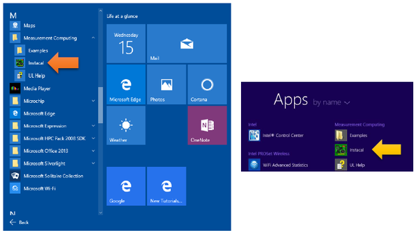 Figure A-II.15: Start the Instacal driver controller program.
 -
You may be prompted with a message box as shown in Figure A-II.16 saying that the previous board name has not been deleted. Press “OK” button.
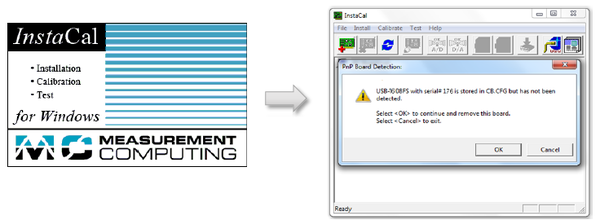 Figure A-II.16: Configure the Instacal driver controller program.
 -
The “Instacal” driver interface will list A/D and D/A board names – e.g. USB-1608FS board and USB-3114 (Figure A-II.17).
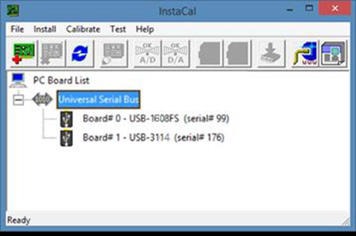 Figure A-II.17: Instacal driver controller program list A/D and D/A board names.
 -
Select USB-3114 and double click on it.
-
In USB-3114 Board Configuration window use the dropdown list and set at the D/A Ranges to +/-10V (default is 0-10V)as shown in Figure A-II-18.
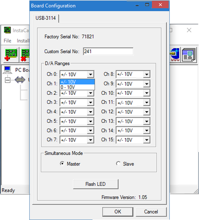 Figure A-II.18: Instacal driver controller program list A/D and D/A board names.
 -
Close “Instacal” driver interface and open NeoScan Optical Bench Manager program.
-
If the “Instacal” driver interface does not list A/D and D/A board names as indicated in Figure A-II-19.
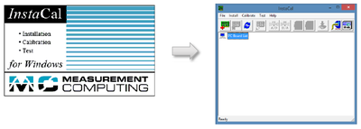 Figure A-II.19: Instacal driver controller program cannot detect A/D and D/A converters.


