Difference between revisions of "NeoScan for Antenna Characterization"
Kazem Sabet (Talk | contribs) |
Kazem Sabet (Talk | contribs) |
||
| Line 1: | Line 1: | ||
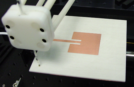
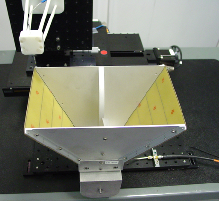
[[Image:NEOWEB11.png|thumb|450px|NeoScan field probe scanning the surface of a microstrip patch antenna at 2.4GHz.]] | [[Image:NEOWEB11.png|thumb|450px|NeoScan field probe scanning the surface of a microstrip patch antenna at 2.4GHz.]] | ||
| − | |||
| − | |||
| − | |||
| − | |||
| − | |||
| − | |||
| − | |||
| − | |||
| − | |||
| − | |||
| − | |||
| − | |||
| − | |||
| − | |||
| − | |||
| − | |||
| − | |||
| − | |||
| − | |||
| − | |||
== A Low-Cost Alternative to Costly Anechoic Chambers and Much More... == | == A Low-Cost Alternative to Costly Anechoic Chambers and Much More... == | ||
| Line 44: | Line 24: | ||
<td> | <td> | ||
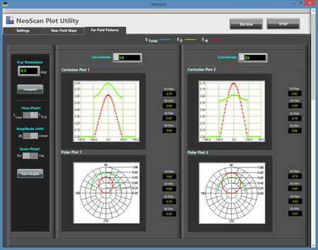
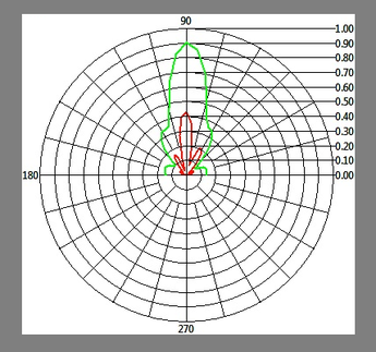
[[Image:NEOWEB13.png|thumb|450px|Computed theta and phi components of the radiation pattern of the S-band patch antenna in the principal planes.]] | [[Image:NEOWEB13.png|thumb|450px|Computed theta and phi components of the radiation pattern of the S-band patch antenna in the principal planes.]] | ||
| + | </td> | ||
| + | </tr> | ||
| + | </table> | ||
| + | |||
| + | == NeoScan vs. Conventional Near-Field Scanning Systems == | ||
| + | |||
| + | The [[NeoScan]] system provides a unique and highly superior alternative to the conventional near-field scanning systems. The [[NeoScan]] probes are optical and have absolutely non-metallic compositions. They are extremely small, can get very close to the surface of the radiating aperture, and provide ultra-wideband operation. Due to their non-invasive nature, [[NeoScan]] probes can generate ultra-near-field scans of the AUT. These can be used as an invaluable tool for diagnostic purposes. For instance, you can examine the inter-element coupling effects in passive and active phased arrays. | ||
| + | |||
| + | The [[NeoScan]] - ANT system comes with an operational software that quickly determines the optimal distance of the probe from the radiating aperture for the fastest scan. The radiation pattern of the AUT is readily computed using a rigorous near-to-far-field transformation without any need for eliminating artifact errors. This is due to the fact that [[NeoScan]] measures the "true" near fields of the AUT without any external perturbations. | ||
| + | |||
| + | In short, with [[NeoScan]], you get a compact portable self-contained system that characterizes your antenna system from the very near fields to the very far fields without requiring considerable real estate. [[NeoScan]] is particularly useful for phase characterization and calibration large antenna arrays. | ||
| + | |||
| + | |||
| + | <table> | ||
| + | <tr> | ||
| + | <td> | ||
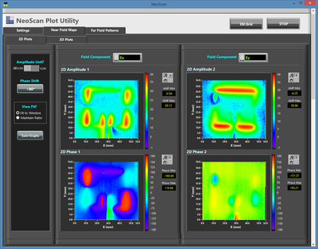
| + | [[Image:NEOWEB7.png|thumb|450px|2D intensity plots of the amplitude and phase of the X and Y components of the electric field on the surface of the patch antenna.]] | ||
| + | </td> | ||
| + | <td> | ||
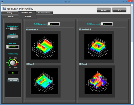
| + | [[Image:NEOWEB9.png|thumb|450px|3D surface plots of the amplitude and phase of the X and Y components of the electric field on the surface of the patch antenna.]] | ||
</td> | </td> | ||
</tr> | </tr> | ||
Revision as of 16:12, 15 January 2016
Contents
A Low-Cost Alternative to Costly Anechoic Chambers and Much More...
NeoScan systems can be used as an essential tool for characterization, test and evaluation of antennas and phased array systems. The radiation patterns of antennas and arrays are traditionally measured in anechoic chambers. The size of the chamber, its architecture and the quality of the surrounding absorbers all affect the chamber's frequency range of operation and the accuracy of the measured results. Anechoic chamber facilities are very expensive, require a large space and are hard to operate and maintain. Compact near-field ranges are smaller replacements for full-sized chambers.
Near-field scanning systems are by far the most compact alternatives for antenna pattern measurement. Yet, conventional near-field scanning systems have substantial downsides. These systems involve metallic radiators that act as receivers for picking up the near field of the antenna under test (AUT). Such metallic pick-up antennas cannot get close to the AUT since they would perturb its near fields. They also limit the operational bandwidth of the system, and their accuracy degrades significantly at lower frequency bands. Sophisticated software tools are often used in conjunction with these systems to de-embed and minimize various errors due to their specific architectures and configurations.
NeoScan vs. Conventional Near-Field Scanning Systems
The NeoScan system provides a unique and highly superior alternative to the conventional near-field scanning systems. The NeoScan probes are optical and have absolutely non-metallic compositions. They are extremely small, can get very close to the surface of the radiating aperture, and provide ultra-wideband operation. Due to their non-invasive nature, NeoScan probes can generate ultra-near-field scans of the AUT. These can be used as an invaluable tool for diagnostic purposes. For instance, you can examine the inter-element coupling effects in passive and active phased arrays.
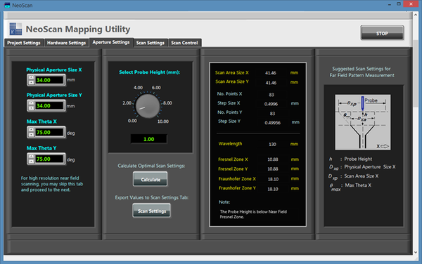
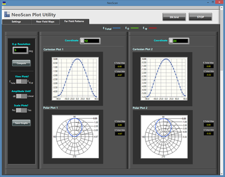
The NeoScan - ANT system comes with an operational software that quickly determines the optimal distance of the probe from the radiating aperture for the fastest scan. The radiation pattern of the AUT is readily computed using a rigorous near-to-far-field transformation without any need for eliminating artifact errors. This is due to the fact that NeoScan measures the "true" near fields of the AUT without any external perturbations.
In short, with NeoScan, you get a compact portable self-contained system that characterizes your antenna system from the very near fields to the very far fields without requiring considerable real estate. NeoScan is particularly useful for phase characterization and calibration large antenna arrays.
The Perfect Solution for Characterizing Ultra-wideband Antenna Systems
Characterization of Ultra-wideband Antenna Systems using near-field scanning is a very challenging task. Conventional near-field scanning systems require different types of metallic antennas with different sizes at different frequency bands.
The Perfect Solution for Characterizing High-Power Antenna Systems
Characterization of high-power active phased arrays is a very challenging task. Special considerations must be taken into account when measuring high-power antenna systems in an anechoic chamber including operator's safety. NeoScan probes can handle field intensities as large as 2MV/m and can even withstand higher radiated power levels. EMAG's unique probe and optical processing technology allows standoff distances as long as 50 meters between the probe location at the aperture of the high-power array and the optical mainframe and processing unit. This enables you to readily characterize very high-power antenna systems very accurately in a totally non-invasive manner without any serious safety or logistic concerns.
