Difference between revisions of "RF.Spice A/D: Getting Started"
Kazem Sabet (Talk | contribs) (→Menus) |
Kazem Sabet (Talk | contribs) |
||
| Line 144: | Line 144: | ||
</table> | </table> | ||
| − | == Toolbars == | + | == Toolbars, Menus & Windows == |
[[RF.Spice A/D]] is mainly controlled by the Toolbox and [[Toolbars]]. [[Toolbars | Toolbars]] are collections of icons that are shortcuts to menu commands, and are located below the [[menus]]. [[RF.Spice A/D]] has a [[main toolbar]] which is common to all modes of operation and is used to control file and simulation functions. It also has two other window-specific [[toolbars]] to control other functions available for specific [[windows]]. [[Toolbars#Schematic_Toolbar |Schematic Toolbar]] appears only when a schematic is the active window. [[Toolbars#Graph_Toolbar |Graph Toolbar]] appears only when a graph is the active window. For a more information on each toolbar, follow these links: | [[RF.Spice A/D]] is mainly controlled by the Toolbox and [[Toolbars]]. [[Toolbars | Toolbars]] are collections of icons that are shortcuts to menu commands, and are located below the [[menus]]. [[RF.Spice A/D]] has a [[main toolbar]] which is common to all modes of operation and is used to control file and simulation functions. It also has two other window-specific [[toolbars]] to control other functions available for specific [[windows]]. [[Toolbars#Schematic_Toolbar |Schematic Toolbar]] appears only when a schematic is the active window. [[Toolbars#Graph_Toolbar |Graph Toolbar]] appears only when a graph is the active window. For a more information on each toolbar, follow these links: | ||
| Line 151: | Line 151: | ||
* [[Toolbars#Schematic_Toolbar | Schematic Toolbar]] | * [[Toolbars#Schematic_Toolbar | Schematic Toolbar]] | ||
* [[Toolbars#Graph_Toolbar | Graph Toolbar]] | * [[Toolbars#Graph_Toolbar | Graph Toolbar]] | ||
| − | |||
| − | |||
| − | |||
| − | |||
<table> | <table> | ||
| Line 168: | Line 164: | ||
</table> | </table> | ||
| − | + | Another important visual element of [[RF.Spice A/D]] is its menu bar located at the top of the screen underneath the title bar. [[Menus | Menus]] provide another convenient way to access many different functions such as file and edit operations, view settings, simulation, as well as a large number of generic parts passive and active elements, digital parts and virtual blocks. The contents of the menu bar changes depending on the active window: | |
| + | |||
| + | * [[Menus#Schematic_Editor_Menus | Schematic Editor Menus]] | ||
| + | * [[Menus#Graph_View_Menus | Graph View Menus]] | ||
| + | * [[Menus#Table_View_Menus | Table View Menus]] | ||
| + | |||
| + | <table> | ||
| + | <tr> | ||
| + | <td> [[File:b2MAN_Fig17.png|thumb|400px|RF.Spice A/D Schematic Menu]] </td> | ||
| + | </tr> | ||
| + | <tr> | ||
| + | <td> [[File:b2MAN_Fig18.png|thumb|400px|RF.Spice A/D Graph and Table Menus]] </td> | ||
| + | </tr> | ||
| + | </table> | ||
[[RF.Spice A/D]] has changed the way [[windows | windows]] are arranged and appear. The biggest difference is that now all [[windows]] are "tabs" in a larger Project window. Projects contain all the files associated with a particular circuit, including any graphs, netlists, and other related files. All Project files will appear in one window with the different Project files as Tab at the bottom left of the window. If you load a new circuit, it will automatically open in a new Project Window. More than one Project can be open at once. To switch to a different view, just click on the Tab that you wish to view. If you right click on a window tab, you will get the contextual pop-up menu, from which you can choose to close the Tab, add a new Tab, or rename the Tab. | [[RF.Spice A/D]] has changed the way [[windows | windows]] are arranged and appear. The biggest difference is that now all [[windows]] are "tabs" in a larger Project window. Projects contain all the files associated with a particular circuit, including any graphs, netlists, and other related files. All Project files will appear in one window with the different Project files as Tab at the bottom left of the window. If you load a new circuit, it will automatically open in a new Project Window. More than one Project can be open at once. To switch to a different view, just click on the Tab that you wish to view. If you right click on a window tab, you will get the contextual pop-up menu, from which you can choose to close the Tab, add a new Tab, or rename the Tab. | ||
| Line 184: | Line 193: | ||
The Project window can be arranged so that the Tabs are displayed side by side or one atop another. To do so select the layout you wish from the Layout button in the toolbar. Any layout chosen will arrange the Tab [[windows]] as indicated by the icon in the menu only for that project. If there are not enough tabs to split as chosen by the Layout button, the program will leave that pane empty. You can then fill it up with new tabs that you create. You can also drag existing [[windows]] to the empty frames. To move [[windows]], drag the window tab to the window that you wish to move the existing window to. | The Project window can be arranged so that the Tabs are displayed side by side or one atop another. To do so select the layout you wish from the Layout button in the toolbar. Any layout chosen will arrange the Tab [[windows]] as indicated by the icon in the menu only for that project. If there are not enough tabs to split as chosen by the Layout button, the program will leave that pane empty. You can then fill it up with new tabs that you create. You can also drag existing [[windows]] to the empty frames. To move [[windows]], drag the window tab to the window that you wish to move the existing window to. | ||
| − | |||
| − | |||
| − | |||
| − | |||
<table> | <table> | ||
<tr> | <tr> | ||
| Line 198: | Line 203: | ||
</tr> | </tr> | ||
</table> | </table> | ||
| − | |||
| − | |||
| − | |||
| − | |||
| − | |||
| − | |||
| − | |||
| − | |||
[[Image:Info_icon.png|40px]] To learn more about building schematics in [[RF.Spice A/D]], see the section on [[B2_schematic| Working with Schematic Editor]]. | [[Image:Info_icon.png|40px]] To learn more about building schematics in [[RF.Spice A/D]], see the section on [[B2_schematic| Working with Schematic Editor]]. | ||
[[Image:Info_icon.png|40px]] To learn more about graphs and data tables in [[RF.Spice A/D]], see the section on [[B2_output | Visualizing Simulation Data Using Graphs and Tables]]. | [[Image:Info_icon.png|40px]] To learn more about graphs and data tables in [[RF.Spice A/D]], see the section on [[B2_output | Visualizing Simulation Data Using Graphs and Tables]]. | ||
| − | |||
| − | |||
| − | |||
| − | |||
| − | |||
| − | |||
| − | |||
| − | |||
| − | |||
[[File:b2MAN_Fig23.png|thumb|250px|RF.Spice A/D Virtual Instrument Panel]] | [[File:b2MAN_Fig23.png|thumb|250px|RF.Spice A/D Virtual Instrument Panel]] | ||
Revision as of 16:55, 2 August 2015
Contents
RF.Spice A/D in a Nutshell
RF.Spice A/D is a powerful simulation environment for analysis and design of analog, digital, RF and mixed-mode circuits. Rather than designing and testing circuits with real physical components in a laboratory with expensive test equipment, RF.Spice A/D allows you to perform accurate and realistic simulations of your circuits without clipping wires or splashing solder. With RF.Spice A/D, editing and simulating circuits is a quick, easy, even enjoyable, process.
RF.Spice A/D consists of a number of tightly integrated tools and utilities that work together seamlessly and provide the ultimate computational power with an intuitive and easy-to-use visual interface. When you start the RF.Spice A/D application, you are in the RF.Spice A/D Workshop, with its Schematic Editor occupying the main window. This is where you assemble your circuit. A circuit is made up of a number of parts like resistors, capacitors, diodes, transistors, voltage and current sources, logic gates, transmission line segments, etc., which are connected to one another using wires. RF.Spice A/D comes with a very large parts database featuring thousands of passive and active devices including generic models and real parts supplied by major semiconductor device manufacturers. Active device models include no less than six distinct MOSFET models including BSIM3 and BSIM4.
Once your circuit is ready for simulation, RF.Spice A/D generates a Netlist input and calls its SPICE engine(s). RF.Spice A/D supports the full Berkeley SPICE 3F5 set of commands, options and models. These include a variety of simulation types such as DC and AC sweeps, transient and Fourier analyses, pole-zero and distortion analyses, network analysis, Monte Carlo and sensitivity analyses, and more. RF.Spice A/D also provides a large number of black-box blocks including all of XSPICE models such as differentiator, integrator and s-domain transfer function blocks and mutual coupling for transformer modeling. Event-driven digital simulation is fully supported as well as A/D and D/A bridge models for mixed-mode simulation. With a comprehensive library of generic and physical transmission line components and multiport devices, you can perform nodal analysis or network analysis of passive and active RF circuits as well as mixed-signal analog/digital/RF circuits.
Using RF.Spice A/D you can perform live simulations, where output data are generated and animated as the simulation proceeds. You can vary the circuit parameters in real time during a live simulation. You can also run a large variety of tests (DC bias, AC, transient, etc.). You can visualize, manipulate and process the output data in the form of graphs or tables in the Data Manager, which is part of the RF.Spice A/D Workshop.
The RF.Spice A/D Device Manager is a separate application you can use for defining or importing new parts or modifying those already in the parts bin. You will often find RF.Spice's large parts database adequate for most practical circuits. However, you can customize and expand the database to meet your growing analysis and design needs. The Device Manager has an integrated Symbol Editor with an array of drawing tools, which you can use to create new device symbols or modify the existing ones.
System Requirements
- A Pentium P5 or later processor
- 1 GB RAM minimum
- Microsoft Windows 7 or 8 operating system
Installation
Download and run the executable installer program from the download link that is provided to you by EMAG Technologies Inc. and follow the installer instructions step by step.
License
The RF.Spice A/D application comes with a node-locked license that works only on the computer for which it was originally generated. After you install RF.Spice A/D on your computer and try to start the program for the first time, it pops up an error message saying it could not locate the license file. This message also displays one or more MAC Addresses specific to the computer on which you have installed the RF.Spice A/D application. A MAC address is a 12-character string that is a combination of letters and numbers. You need to email this MAC address to us so we can generate a license file for you. Once you receive the ".LIC" license file from us, place it in the "Licenses" folder of your installation directory. You are now set to go!
An Overview of RF.Spice A/D Workshop
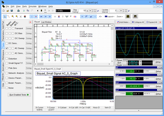
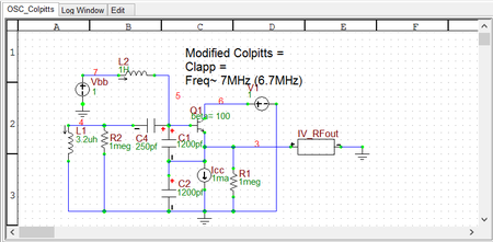
RF.Spice A/D allows you to enter a circuit design in its schematic editor, run simulations on your circuit, and view the simulation results. All this is done in the RF.Spice A/D Workshop. To open the Workshop, double-click the RF.Spice A/D icon on your desktop. When you start the application, a blank circuit appears in the Main Window. This is the Schematic Editor window, where you define and place your parts, connect them using wires and build up your circuit.
RF.Spice A/D has two distinct and independent simulators: Mixed-Mode and Digital. Each of these two simulators has its own schematic mode. The mixed-mode simulator simulates analog and mixed analog/digital circuits. If your circuit is analog or mixed-mode, then the mixed-mode schematic and simulator are used. If your circuit is pure digital, then the digital schematic and simulator are evoked, which allow for interactive inputs and outputs. The selection of the appropriate schematic mode and simulation engine is done automatically by RF.Spice A/D. In other words, you do not have to specify the type of your circuit or choose a particular simulation engine type.
The RF.Spice A/D Workshop consists of a number of visual elements:
- Toolbox
Toolbox Overview
One of the important visual elements of RF.Spice A/D is its Toolbox located on its left side panel. The Toolbox allows you quick access and navigation to all your project properties, parts in the current project, parts in your custom palette, and all the parts in the database. It also contains the Test Panel and all the graph settings and controls. From the toolbox, you can quickly select parts, set various parameters for the analysis of your circuit and customize your output data and graphs.
RF.Spice's Toolbox has a number of tabs:
- Parts Bin
- Workspace
- Wizards
- Edit Plots (Only when a graph window is active)
- Edit Graph (Only when a graph window is active)
- Tracker (Only when a graph window is active)
- Edit Axes (Only when a graph window is active)
Parts Bin
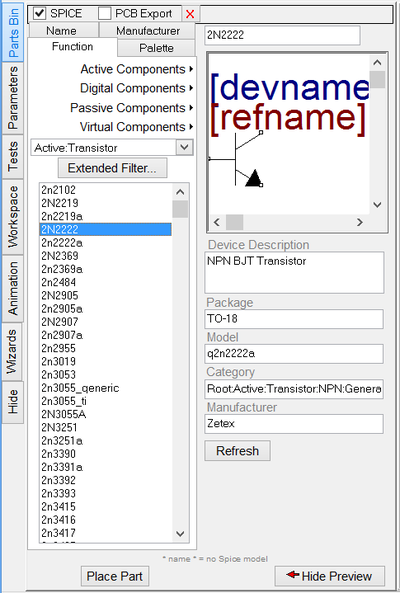
Besides RF.Spice's standard database browser where you can search a part by name or filter by category or keyword, the Parts Bin of the toolbox allows you to pick and place the exact part you want by function, manufacturer or name from a pop-up menu. Clicking on the "Parts Bin" tab allows you to scroll through a parts list grouped by function, or by manufacturer or by name. "Parts Palette" allows you to store your most frequently used parts available in your company's inventory for quick and easy access. You can add and remove parts as your requirements change.
The first time you select a part, the program will seem to hang, but it is indeed pulling data from the parts database. This might take a few seconds and is completely normal. More importantly, this will only happen the FIRST time you select a part. Once the program fills in the data, subsequent device selections will take place without a pause.
![]() For further discussion of how to choose and place parts, please see the section on Choosing and Placing Parts.
For further discussion of how to choose and place parts, please see the section on Choosing and Placing Parts.
Circuit Parameters
The Parameters tab of the toolbox contains a list of all the parts in your circuit whose parameters can be changed, such as resistors, capacitors, etc. Next to each part is its current value. The purpose of this area is to allow quick value changes to part values while a live simulation is running.
![]() To learn more about RF.Spice's live parameters, please refer to the section on Circuit Parameters.
To learn more about RF.Spice's live parameters, please refer to the section on Circuit Parameters.
Circuit Tests
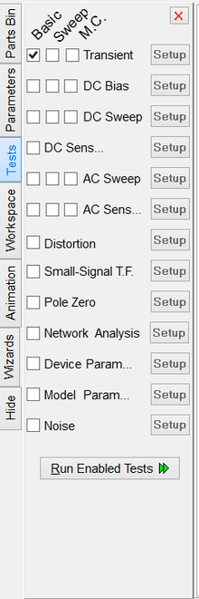
In RF.Spice A/D, "Predefined Tests" and "Live Simulations" are now two distinct simulation modes. Live simulations refer to perpetual time-domain simulations that start at t = 0 and end only when you pause or reset them. Tests are pre-defined analysis types that you run on your circuit to see how it behaves under various domains. DC Bias (Operating Point), AC, Transient are some examples of test types you will frequently run in RF.Spice A/D. Each test can be selected, set up, and run from the pull down menu in the Tests tab of the toolbox. Unlike live simulations, tests are NOT interactive, and the results are displayed on a graph or in a table, NOT on virtual instruments.
![]() For detailed descriptions on each Test, refer to the section on Tests.
For detailed descriptions on each Test, refer to the section on Tests.
Circuit Animation
Circuit Animation allows graphical and text representation of the circuit state on the schematic using wire/part colors as well as symbols and text to represent the voltage, current and power states of the circuit while a live simulation is running. More details about live data visualization can be found in the section on Circuit Animation.
Project Management
The Workspace tab of the toolbox allows you total control over the all the files associated with a circuit. The workspace is set up in a collapsible tree-based structure. Each project can be expanded to show all the files associated with that project, including the circuit itself, the simulations, simulation results, and associated graphs. You can add new files or close existing files in the workspace by highlighting the project or file, opening the File Menu and choosing the appropriate command.
Circuit Wizards
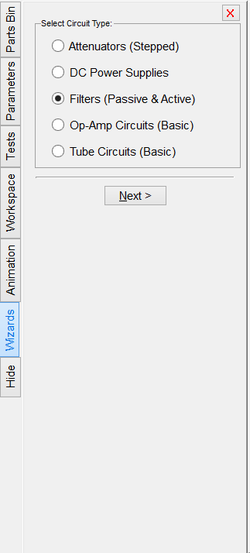
The idea behind the Circuit Wizards is easy circuit creation. Just select the type of circuit that you wish to create, fill in a few choices and the rest of the work is done for you. You may select to place the new circuit directly into your existing circuit or place it into a blank circuit to start a new design.
Graphing and Plot Controls
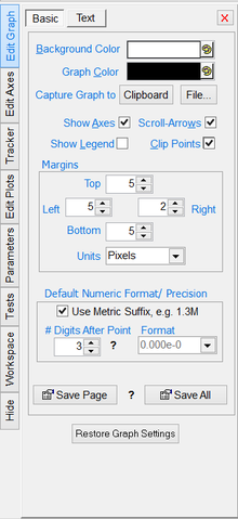
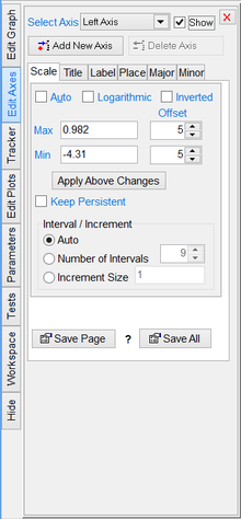
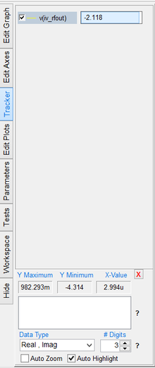
When a graph window is active, the toolbox contains four additional tabs: "Edit Graph", "Edit Axes", "Tracker" and "Edit Plots". All aspects of the graph are controlled from these tabs. The Edit Graph tab controls the appearance of the graph itself, including the graph size, color and text on the graph, as well as the plot colors. The Tracker tab allows you to view the various plots on the graph and information relevant to the plots. From the Edit Axes tab, you can adjust the individual axes, their bounds and appearance. The Edit Plots tab controls the individual plots in the graph and how they appear. Here you can add and remove plots from the graph as well as making custom plots using a built-in function library.
![]() To learn more about graphs and plotting data in RF.Spice A/D, see the section on Visualizing Simulation Data Using Graphs and Tables.
To learn more about graphs and plotting data in RF.Spice A/D, see the section on Visualizing Simulation Data Using Graphs and Tables.
Toolbars, Menus & Windows
RF.Spice A/D is mainly controlled by the Toolbox and Toolbars. Toolbars are collections of icons that are shortcuts to menu commands, and are located below the menus. RF.Spice A/D has a main toolbar which is common to all modes of operation and is used to control file and simulation functions. It also has two other window-specific toolbars to control other functions available for specific windows. Schematic Toolbar appears only when a schematic is the active window. Graph Toolbar appears only when a graph is the active window. For a more information on each toolbar, follow these links:
Another important visual element of RF.Spice A/D is its menu bar located at the top of the screen underneath the title bar. Menus provide another convenient way to access many different functions such as file and edit operations, view settings, simulation, as well as a large number of generic parts passive and active elements, digital parts and virtual blocks. The contents of the menu bar changes depending on the active window:
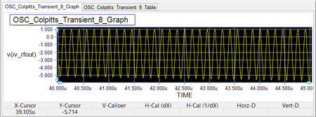
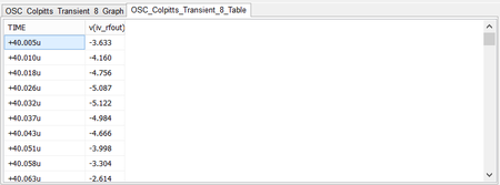
RF.Spice A/D has changed the way windows are arranged and appear. The biggest difference is that now all windows are "tabs" in a larger Project window. Projects contain all the files associated with a particular circuit, including any graphs, netlists, and other related files. All Project files will appear in one window with the different Project files as Tab at the bottom left of the window. If you load a new circuit, it will automatically open in a new Project Window. More than one Project can be open at once. To switch to a different view, just click on the Tab that you wish to view. If you right click on a window tab, you will get the contextual pop-up menu, from which you can choose to close the Tab, add a new Tab, or rename the Tab.
For more specific information on each type of window, refer to the specific windows section below.
The Project window can be arranged so that the Tabs are displayed side by side or one atop another. To do so select the layout you wish from the Layout button in the toolbar. Any layout chosen will arrange the Tab windows as indicated by the icon in the menu only for that project. If there are not enough tabs to split as chosen by the Layout button, the program will leave that pane empty. You can then fill it up with new tabs that you create. You can also drag existing windows to the empty frames. To move windows, drag the window tab to the window that you wish to move the existing window to.
![]() To learn more about building schematics in RF.Spice A/D, see the section on Working with Schematic Editor.
To learn more about building schematics in RF.Spice A/D, see the section on Working with Schematic Editor.
![]() To learn more about graphs and data tables in RF.Spice A/D, see the section on Visualizing Simulation Data Using Graphs and Tables.
To learn more about graphs and data tables in RF.Spice A/D, see the section on Visualizing Simulation Data Using Graphs and Tables.
Virtual Instruments
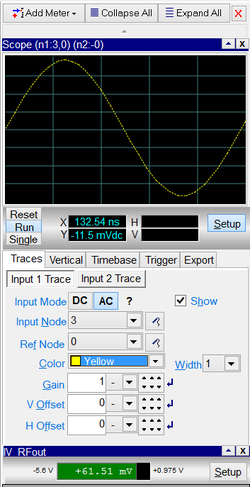
A very useful and important feature of RF.Spice A/D is the Virtual Instruments. Now you have ten instruments to manipulate and measure your circuit. Click on each instrument below to see a detailed description of it.
The specific parameters of each instrument are set using its "setup" button. Pressing the “Setup” button toggles the size of the virtual instrument window. Most instruments have two or more tabs in their settings section containing a number of parameters that can be adjusted. When the setup is complete, press the "Setup" button once again to make the instrument only as tall as its title bar.
